Scheduling methods for wireless networks

a wireless network and scheduling method technology, applied in the field ofwireless communications, can solve the problems of limiting the power of transmitters, limiting data capacity, signal interference, etc., and achieve the effect of maximizing network throughput and minimizing network total power

Inactive Publication Date: 2006-03-02
RGT UNIV OF CALIFORNIA
View PDF26 Cites 168 Cited by
  • Summary
  • Abstract
  • Description
  • Claims
  • Application Information

AI Technical Summary

Benefits of technology

[0005] The invention concerns routing, scheduling, and power control methods for single and multi-hop wireless networks. A multi-hop network is one in which source and destination nodes may communicate directly or through relay nodes. Nodes in single hop networks communicate without use of relay nodes. Embodiments o

Problems solved by technology

Limitations in the wireless communication model for networks include signal interference and power limitations, which both constrain data capacity.
Signal interference is the natural interference inherent in wireless communications.
Power limitations arise from communication standards, e.g., the Federal Communication Commission standards in the United States, that

Method used


Image

  • Scheduling methods for wireless networks
  • Scheduling methods for wireless networks
  • Scheduling methods for wireless networks

Examples


experimental simulation examples

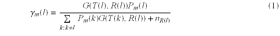
[0097] To illustrate the invention, we will now discuss some simulation examples in the next section.

example 1

Hierarchical Scheduling (Example 1)

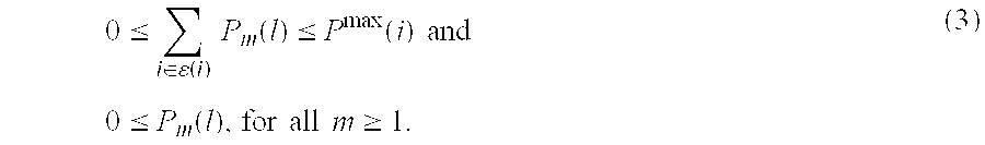
[0098] We consider a large fully connected wireless network consisting of 80 nodes and 150 links as shown in FIG. 1, distributed over a 200 m×200 m field. The network was divided into 16 clusters labeled by integers 1, 2, . . . 16, and each cluster consists of 5 or 6 nodes and 8 or 9 links. A link belongs to a cluster if the transmitting node is within or on the boundary of that cluster. Moreover, each link in the network belongs to exactly one cluster. The minimum average rate on all links in the network is set to the same value. The peak power of all links is identically set to 1 Watt and W′=106. We applied our hierarchical approach over the entire network by dividing it into edge sets in 3 different ways denoted by cluster schedules X, Y and Z. Cluster schedule X schedules a single edge set containing all 16 clusters. Cluster schedule Y schedules two edge sets each consisting of clusters in a checker board pattern. i.e., {1, 3, 6, 8, 9, 11, 14, ...

example 2

String Topology

[0103] A string topology consists of a row of nodes connected by means of directed links as shown in FIG. 4. This topology is useful as a transport network to carry data through short hops but over potentially long total distances through relay nodes. Node 1 is the source of data and node 5 is the sink. Each node in this example has an omnidirectional antenna, and all nodes have identical peak transmission power constraints of 1 Watt. The path-loss between nodes is modeled as an inverse square of the distance, i.e., G⁡(i,j)=1d⁡(i,j)2.

The ambient noise power at all the nodes is assumed to be constant. We compare the maximum throughput of the single session between node 1 to node 5 achieved by our link scheduling policy to a TDMA scheduling policy. The TDMA policy schedules exactly one link at a time, activating each link at maximum power for a fourth of the time. We plot the ratio of throughputs achieved by the our link scheduling algorithm to TDMA with increasing v...


PUM


Abstract

The invention concerns routing, scheduling, and power control methods for single and multi-hop wireless networks. A multi-hop network is one in which source and destination nodes may communicate directly or through relay nodes. Nodes in single hop networks communicate without use of relay nodes. Embodiments of the invention may produce an optimal schedule to provide for the best-case goal for a given parameter. In a preferred embodiment, total power is the parameter and total power is minimized for the network. In another preferred embodiment, data throughput is the parameter, and throughput is maximized for the network.

Description

TECHNICAL FIELD [0001] The field of the invention is wireless communications. The invention is particularly concerned with wireless networks, including single hop and multi-hop networks. BACKGROUND ART [0002] Using wireless radio frequency transmissions provides great freedom to configure networks. Wireless models become more popular because inconvenience and expenses associated with physical connectivity, i.e., through wires, are eliminated. The wireless model is also generally more flexible in that the potential paths for communications are not constrained by any wired connection. [0003] Limitations in the wireless communication model for networks include signal interference and power limitations, which both constrain data capacity. Signal interference is the natural interference inherent in wireless communications. Power limitations arise from communication standards, e.g., the Federal Communication Commission standards in the United States, that limit the power that transmitters...

Claims


Application Information

Patent Timeline
IPC IPC(8): H04B7/00H04B17/00H04L12/28H04L12/56
CPCH04W28/22H04W40/00H04W40/08H04W52/267Y02B60/50H04W72/082H04W72/1231H04W84/18H04W52/346Y02D30/70H04W72/542H04W72/541
Inventor CRUZ, RENE L.SANTHANAM, ARVIND V.
Owner RGT UNIV OF CALIFORNIA
Why Eureka
Try Eureka