Envelope detector with DC level shifting

a detector and level shifting technology, applied in the field of envelope detectors, can solve the problems of increasing the overall cost of an envelope detector, generating undesirable dc offset in its dc output signal,

Inactive Publication Date: 2006-03-02
AVAGO TECH INT SALES PTE LTD
View PDF1 Cites 14 Cited by
  • Summary
  • Abstract
  • Description
  • Claims
  • Application Information

AI Technical Summary

Problems solved by technology

Unfortunately, a bias current applied to the diode rectifier of an envelope detector may generate an undesirable DC offset in its DC output signal.
Unfortunately, a differential amplifier for subtracting a reference DC offset from a DC output signal may increase

Method used


Image

  • Envelope detector with DC level shifting
  • Envelope detector with DC level shifting
  • Envelope detector with DC level shifting

Examples


Embodiment Construction

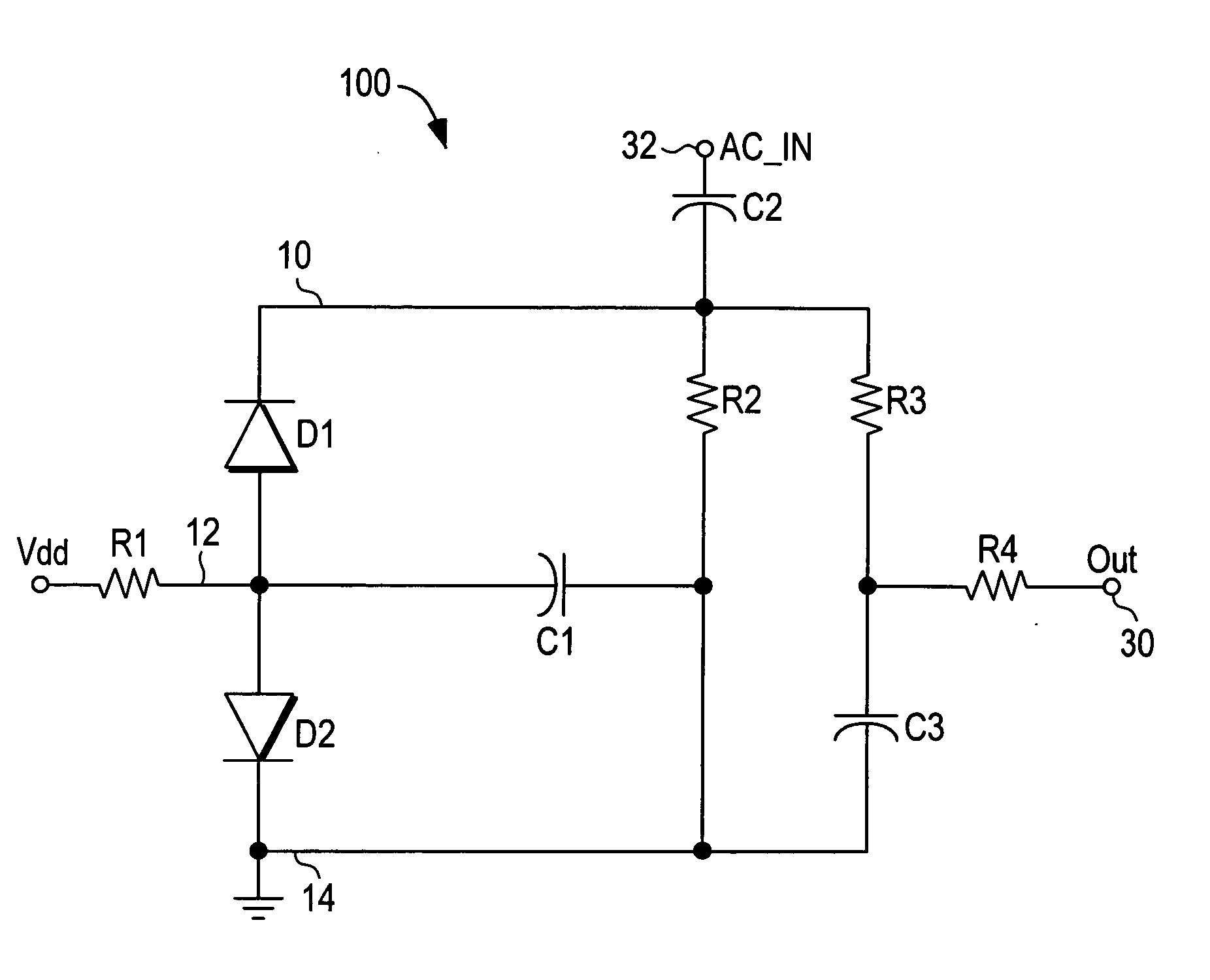
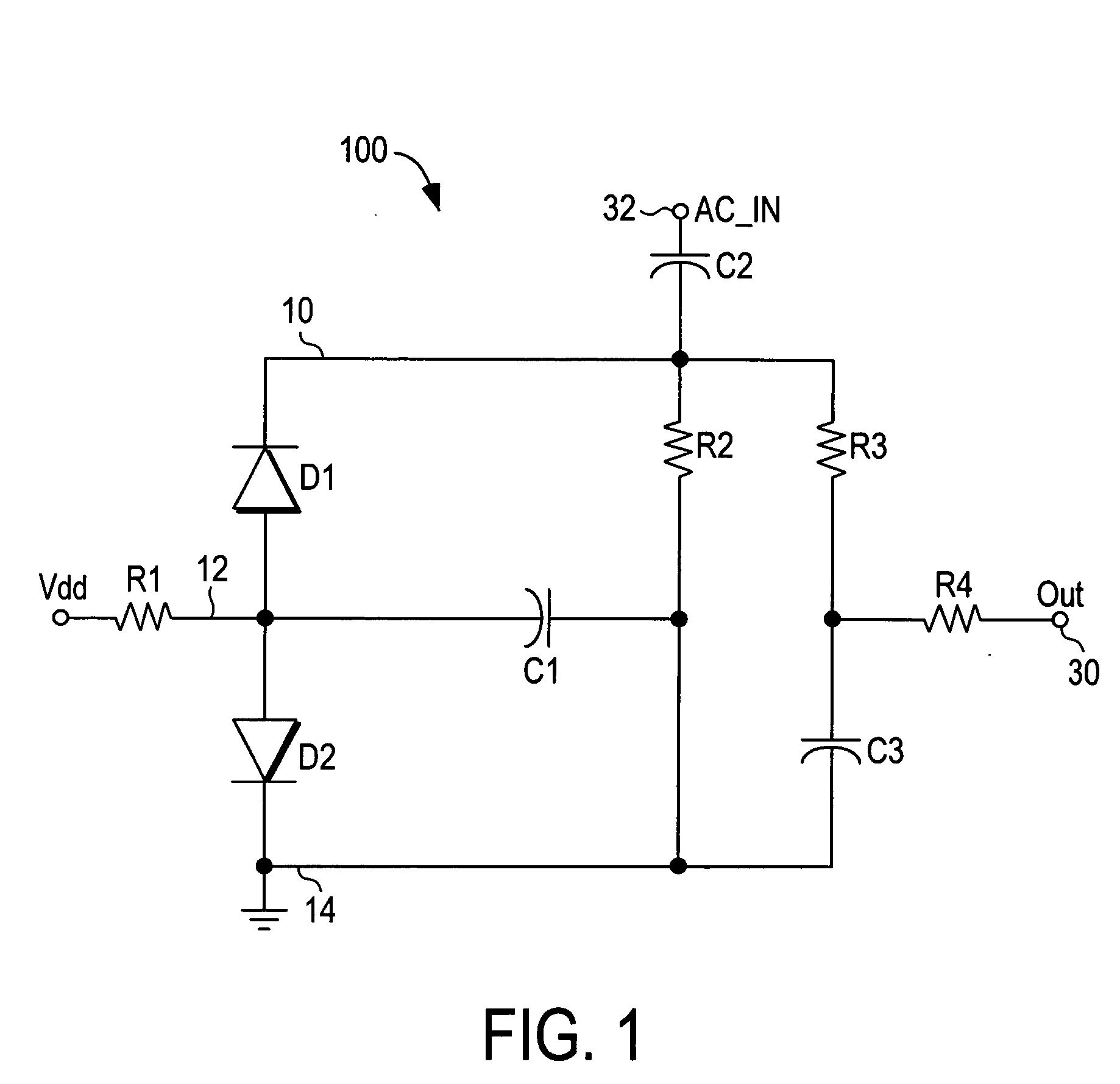
[0012]FIG. 1 shows an envelope detector 100 according to the present teachings. The envelope detector 100 generates a DC output signal at an output node 30 that is proportional to a peak envelope voltage of an AC input signal applied at an input node 32. In one embodiment, the AC input signal applied at the input node 32 is an RF signal.

[0013] The envelope detector 100 includes a pair of diodes D1 and D2. The diodes D1 and D2 are biased so that a DC voltage drop across the diode D1 between a pair of nodes 10 and 12 is substantially similar to a voltage drop across the diode D2 between the node 12 and a ground node 14 but of opposite polarity. The diode D1 is biased to its threshold of conduction by a bias current from a source voltage Vdd through a resistor R1, through the diode D1, through a resistor R2, and then to ground. The diode D2 is biased by a bias current from the source voltage Vdd through the resistor R1, through the diode D2, and then to ground.

[0014] The presence of ...


PUM


Abstract

An envelope detector that does not generate an undesirable DC offset at its DC output signal. An envelope detector according to the present teachings includes a circuit for performing a DC level shift on an AC input signal applied to the envelope detector such that a magnitude of the DC level shift is proportional to a peak envelope of the AC input signal.

Description

BACKGROUND [0001] An envelope detector is an electronic circuit that may be used to detect an amplitude envelope of an AC input signal. For example, an envelope detector may generate a DC output signal that is proportional to an amplitude envelope of an RF input signal. Applications for envelope detectors include generating a feedback signal for controlling the power of an RF transmitter. [0002] An envelope detector may generate a DC output signal by performing a half wave rectification on an AC input signal using a diode rectifier. A diode rectifier in an envelope detector may be biased so that it responds to a relatively small amplitude AC input signal. For example, a bias current may be applied to bias a diode rectifier at its threshold of conduction. Unfortunately, a bias current applied to the diode rectifier of an envelope detector may generate an undesirable DC offset in its DC output signal. [0003] An external differential amplifier may be employed to subtract off the undesi...

Claims


Application Information

Patent Timeline
IPC IPC(8): H04B1/16
CPCG01R19/04
Inventor VICE, MICHAEL W.
Owner AVAGO TECH INT SALES PTE LTD
Why Eureka
Try Eureka