
System for determining the relative position of a second farm vehicle in relation to a first farm vehicle

a technology which is applied in the field of system for determining the relative position of a second farm vehicle in relation to a first farm vehicle, can solve the problems of undesirable erroneous steering process inability to guarantee parallel travel, and increase the directional and speed specifications of the second vehicle, so as to prevent errors in the determined relative position and reduce the accuracy of absolute positions

Active Publication Date: 2006-03-02
DEERE & CO
View PDF2 Cites 64 Cited by
  • Summary
  • Abstract
  • Description
  • Claims
  • Application Information

AI Technical Summary

Benefits of technology

[0013] The above structure assures that both position sensing devices operate in the same reception mode to thereby prevent errors in the determined relative position caused by differing numbers or signal qualities of the satellites received by the position sensing devices. The fact that under certain circumstances the accuracy of the absolute positions can be reduced has no negative effect here.

Problems solved by technology

On one hand, steering data in the form of speed and directional data can be transmitted from the first vehicle to the second vehicle (see DE 100 64 860 A and JP 04 101 206 A), but this type has the disadvantage that possible errors in the directional and speed specifications to the second vehicle add up over time to large errors in the position information so that parallel travel is not always guaranteed.
If different reception conditions for the two receivers exist, caused for example by the shading of one satellite for the first receiver (e.g., on the edge of a field covered by trees where the vehicle travels) while the second vehicle travels further inward in the non-shaded center of the field, errors result in the relative position which can lead to undesirable erroneous steering processes of the second vehicle.
These means, however, are only provided for a single vehicle and cannot solve the problem of different reception conditions of two receivers.
This as well cannot solve the problem of different reception conditions of receivers on two vehicles.

Method used


Image

  • System for determining the relative position of a second farm vehicle in relation to a first farm vehicle
  • System for determining the relative position of a second farm vehicle in relation to a first farm vehicle
  • System for determining the relative position of a second farm vehicle in relation to a first farm vehicle

Examples


Embodiment Construction

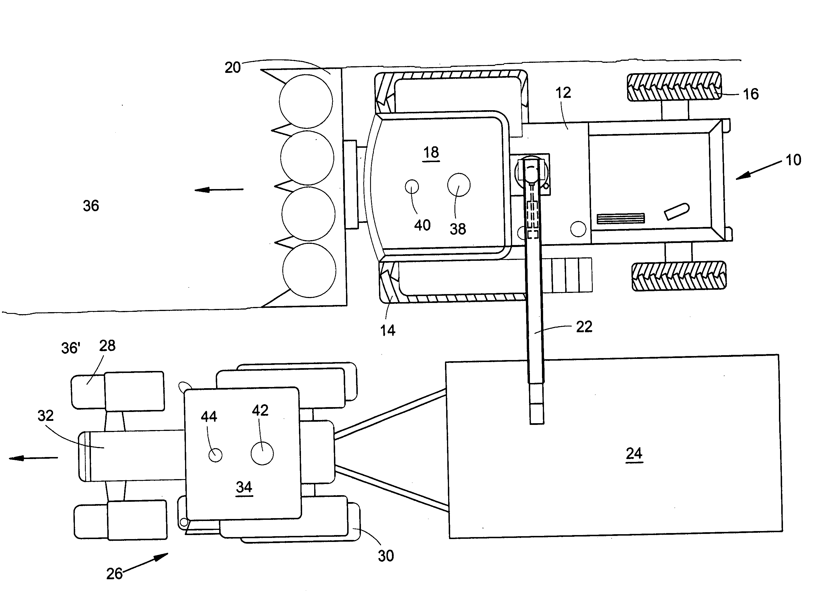
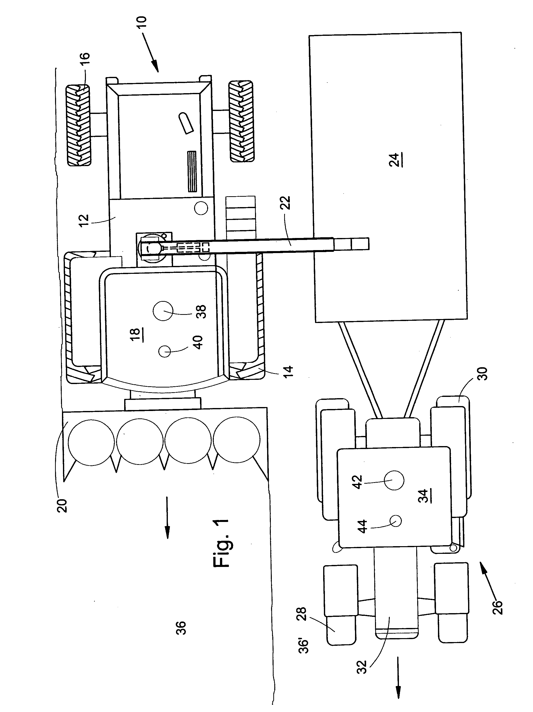
[0023] A first farm vehicle 10 being a type of automated crop chopper shown in FIG. 1 is constructed on a frame 12, supported by front-driven wheels 14 and steerable rear wheels 16. The harvester 10 is operated from a driver's cab 18, from which a crop receiving device 20 can be viewed. The crop receiving device 20, the Crop such as corn, grass or the like is picked up from the ground by the crop receiving device 20 and is fed to a chopper drum, which shreds the crop and passes it on to a conveying device. The crop is conveyed from the vehicle 10 to a trailer 24 traveling next to the vehicle via a discharge auger or conveyor 22 that can pivot about a vertical axis.

[0024] The trailer 24 is pulled by a second farm vehicle 26 shown as a tractor, which includes front steerable wheels 28 and rear-driven wheels 30 rotatably mounted on and supporting a frame 32 having a driver's cab 34.

[0025] The first vehicle 10 harvests plants from a field 36, corn in the illustrated example, which is ...


PUM


Abstract

The entire right, title and interest in and to this application and all subject matter disclosed and / or claimed therein, including any and all divisions, continuations, reissues, etc., thereof are, effective as of the date of execution of this application, assigned, transferred, sold and set over by the applicant(s) named herein to Deere & Company, a Delaware corporation having offices at Moline, Ill. 61265, U.S.A., together with all rights to file, and to claim priorities in connection with, corresponding patent applications in any and all foreign countries in the name of Deere & Company or otherwise.

Description

FIELD OF THE INVENTION [0001] The invention relates generally to a system for determining the relative position of a second farm vehicle in relation to a first farm vehicle, wherein the first vehicle and the second vehicle are equipped to perform jointly an operation on a field that is to be cultivated. The first vehicle contains a first satellite-supported position sensing device equipped to receive signals from several satellites and to provide position data of the first vehicle. The second vehicle contains a second satellite-support position sensing device equipped to receive signals from several satellites and to make position data of the second vehicle available. A data transmission connection exists between the first vehicle and the second vehicle, and the position data of the first vehicle can be transmitted to a computer of the second vehicle or vice versa. The computer provides data with respect to the relative position of the second vehicle relative to the first vehicle ba...

Claims


Application Information

Patent Timeline
IPC IPC(8): G01C21/36
CPCA01B69/007
Inventor METZLER, PATRICKFLOHR, WERNERHOH, MICHAEL
Owner DEERE & CO
Learn More