
Storage system and a storage management system

Inactive Publication Date: 2006-03-02
GOOGLE LLC
View PDF9 Cites 1418 Cited by
  • Summary
  • Abstract
  • Description
  • Claims
  • Application Information

AI Technical Summary

Benefits of technology

[0010] As described above, in the IP-SAN, it is required to set the VLANs to a switch for limiting the communication range and to set the discovery domains to the name management device for limiting the discovery range and further to secure the matching of these settings. For setting the VLANs and the discovery domains as keeping both matched to each other, the prior art is insufficient because it is arranged on the presumption that the zone is set merely to the switch. Hence, the prior art is required to be improved.
[0011] In order to solve the foregoing problem, therefore, the present inventors propose the below-described invention. The invention discloses a storage system, which comprises a storage means for storing a topology table for saving connecting relation among physical ports of one or more storage devices, physical ports of one o

Problems solved by technology

For setting the VLANs and the discovery domains as keeping both matched to each other, the prior art is insufficient because it is arranged on the presumption that the zone is set merely to the switch.

Method used


Image

  • Storage system and a storage management system
  • Storage system and a storage management system
  • Storage system and a storage management system

Examples


first embodiment

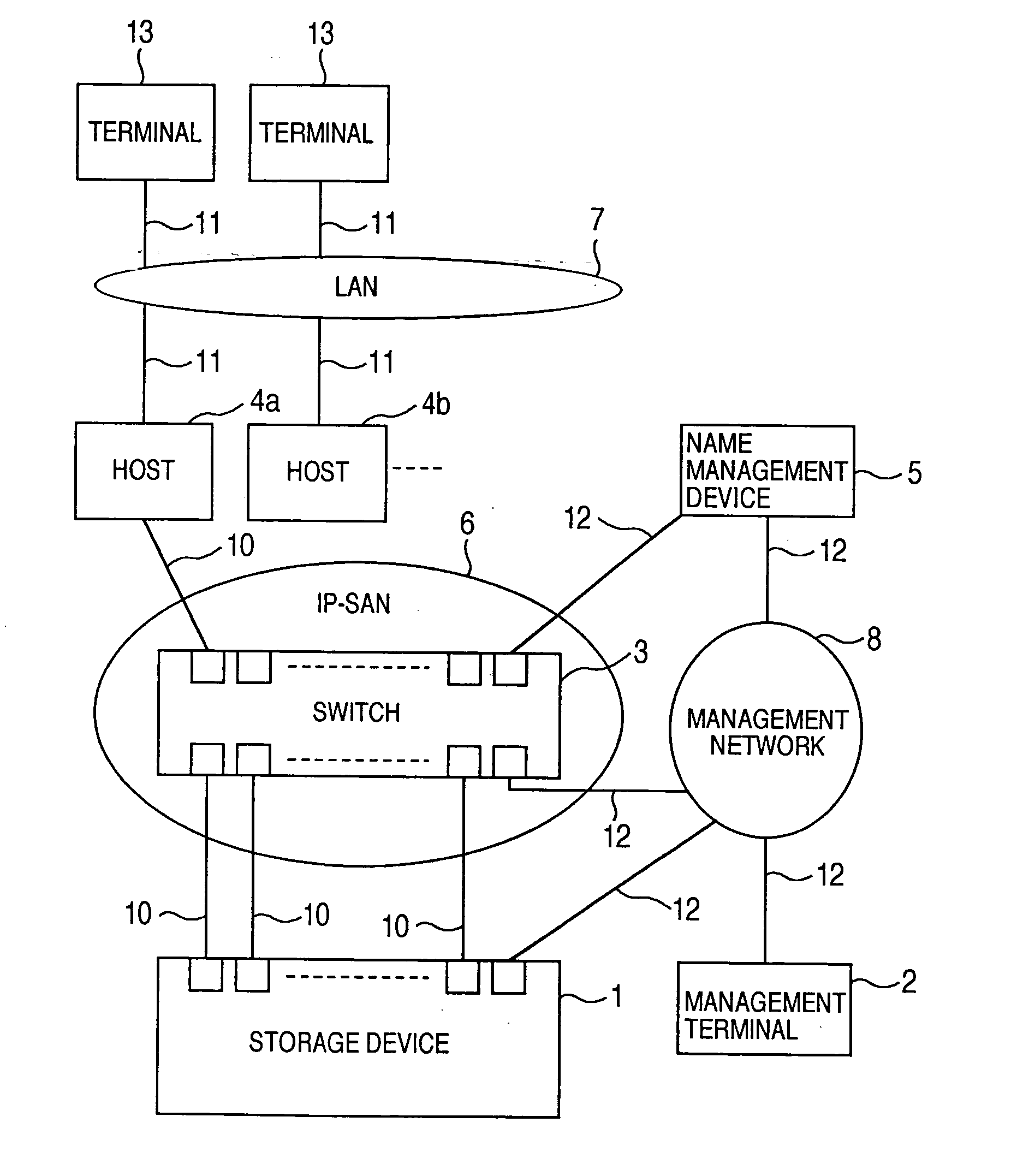
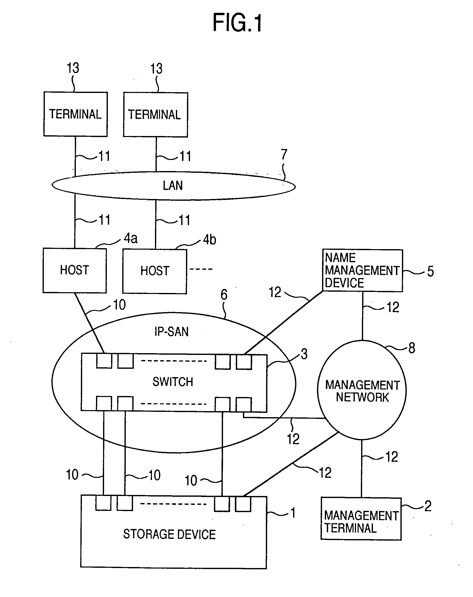
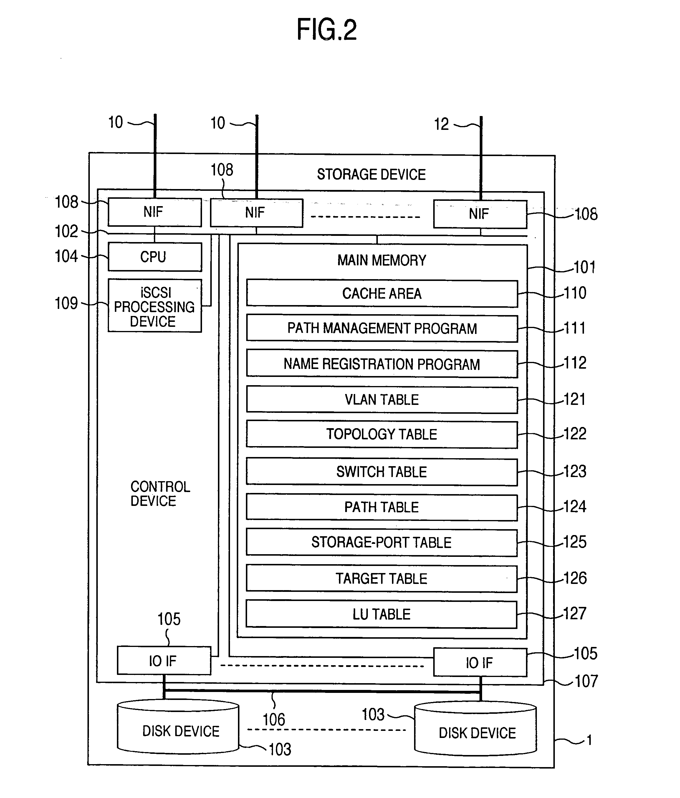
[0060]FIG. 1 shows an exemplary arrangement of the system according to the invention. The system of this embodiment includes a storage device 1 serving as a storage system having a function of communicating with a host 4 through iSCSI and one or more storage devices, a management terminal 2 to be used by a system administrator for setting the storage device 1, a switch 3 operating as a packet transfer device for transferring packets, hosts 4a and 4b (collectively referred to as the “host 4”) having a function of communicating with the storage device 1 through the use of iSCSI, a terminal 13 to be used by an end user or the like for utilizing services provided by the host 4, a name management device 5 for unifying management of the iSCSI names of the host 4 and the storage device 1, an IP-SAN 6 operating as an IP network for communication between the host 4 and the storage device 1 through iSCSI, and communication between the host 4 or the storage device 1 and the name management dev...

second embodiment

[0260] The second embodiment is concerned with a system including storage management device 9 for managing of plural storage devices 1. The storage management device 9 makes it easier to manage the path in a system composed of plural storage devices 1 by managing the information concerned with the plural storage devices.

[0261]FIG. 24 shows an exemplary arrangement of the system according to the second embodiment, In this system, the storage devices 1a and 1b (collectively referred to as the “storage device 1”) are connected with the IP-SAN 6 and the management network 8 with the communication lines 10 and 12, respectively. Further, the storage management device 9 is connected with the management network 8 through the communication line 12. The management terminal 2 is not included in this system.

[0262]FIG. 25A shows an exemplary arrangement of the storage management device 9. This device 9 is a computer including a main memory 901, a communication line 902, a disk device 903, a CPU...


PUM


Abstract

A storage device managing one or more logical volumes is connected with a name management device through an IP-SAN 6 composed of a switch. The storage device stores a topology table saving connecting relation among physical ports of host, physical ports of the storage device and physical ports of the switch, reads an identifier of the host and an identifier of the logical volume, selects a unused first physical port of the switch by referring to the topology table, selects a second physical port of the switch connected with the storage device, registers a group composed of the host and the logical volume with the name management device, and executes a configuration of allowing packets to be transferred between the first and the second physical ports with respect to the switch.

Description

BACKGROUND OF THE INVENTION [0001] The present invention relates to a system having one or more storage devices and an information processing apparatus connected with the storage devices through a network. [0002] In place of a configuration having a storage device directly connected with a computer (often referred to as a “host” or a “host computer”), today, another configuration is prevailing in which one or more storage devices are connected with a plurality of hosts through a network. The connecting configuration of storage device(s) through a network is called a storage area network (referred to as a “SAN”). The SAN has been heretofore configured by using fibre channel technology (referred to as “FC”). Hereafter, a SAN configured by using the FC technology is called an FC-SAN. [0003] Conventionally, in the FC-SAN, hosts and storage devices are divided into groups each called a zone through the use of a function of a switch called zoning in order to limit accessible hosts to the ...

Claims


Application Information

Patent Timeline
IPC IPC(8): G06F12/16
CPCG06F3/0605G06F3/0622H04L41/0866G06F3/067G06F3/0635
Inventor SHIGA, KENTANAKATSUKA, DAIKI
Owner GOOGLE LLC
Learn More