Storage subsystem
a storage subsystem and subsystem technology, applied in the field of storage subsystems, can solve the problems of inadequate installation method of hdd while retaining the conventional storage device installation method, and achieve the effects of improving stability or reliability, simplifying maintenance-related manipulation and raising the cooling efficiency of the storage subsystem
- Summary
- Abstract
- Description
- Claims
- Application Information
AI Technical Summary
Benefits of technology
Problems solved by technology
Method used
Image
Examples
first embodiment example
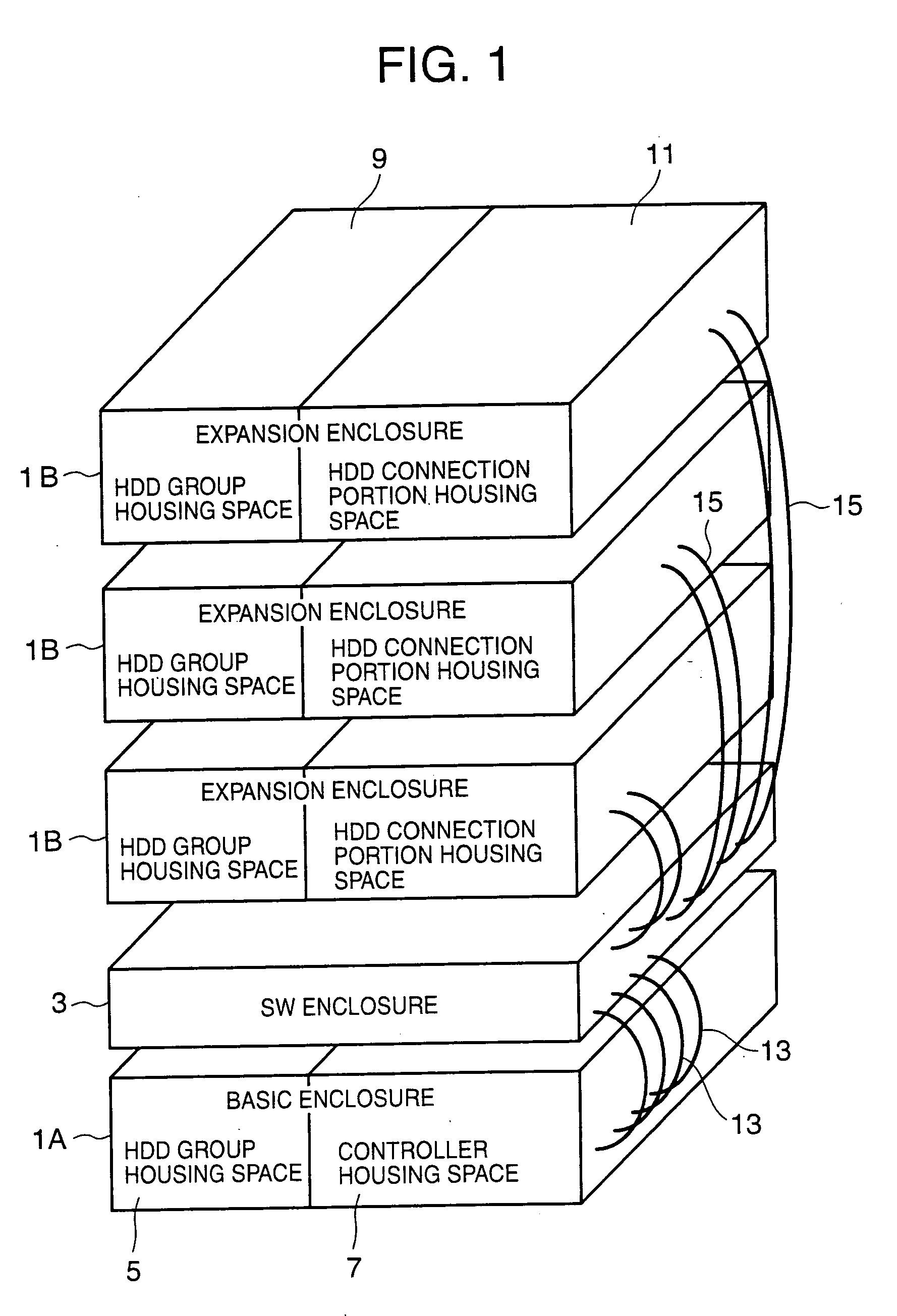
[0056]FIG. 1 provides a schematic external view of a storage subsystem according to a first embodiment example of an embodiment of the present invention.
[0057] A storage subsystem 1 is a RAID (Redundant Array of Inexpensive Disks) system, for example. The storage subsystem 1 comprises a basic enclosure 1A, a plurality of (or a single) expansion enclosures 1B, 1B, . . . , and a switch enclosure (abbreviated to ‘SW enclosure’ hereinafter) 3 that electrically connects the basic enclosure 1A and expansion enclosures 1B.
[0058] The SW enclosure 3 comprises a switch device (not shown). An HDD connection portion (not shown) within the expansion enclosure 1B, which will be described subsequently, is connected to the switch device via a cable 15. Further, controller units (not shown) in the basic enclosure 1A (described subsequently) are connected to the switch device via cables 13. As a result, the controller units are able to access the HDDs in the expansion enclosure 1B via the switch de...
second embodiment example
[0132] In the second embodiment, the method of withdrawing the HDD group installation drawer 19 differs from that of the first embodiment example.
[0133] Withdrawal methods include, for example, a method (referred to as the ‘integrated withdrawal method’ hereinafter) in which the HDD group installation drawer 19 is withdrawn integrally with the rear-side parts (the back plane 17 and the parts that exist further in the depth direction than the back plane 17) and a method (referred to as the ‘separate withdrawal method’ hereinafter) in which the HDD group installation drawer 19 is withdrawn separately from the back plane 17. Variations on each withdrawal method will be described below.
[0134] (A) Integrated Withdrawal Method
[0135]FIG. 12A shows a first variation on the integrated withdrawal method.
[0136] According to the first variation, a cable (hereinafter ‘external cable’) 77, which is connected to the rear-side connector 43 of the power supply unit 39, controller units 37A, 37B,...
third embodiment example
[0150] In the third embodiment example, the removal method for the HDD 23 differs from that of the first embodiment example.
[0151]FIG. 14A shows a first variation on the removal method for the HDD 23.
[0152] In the first variation, an elastic body (a spring, for example) 511 whose height runs vertically is provided between the HDD mounting portion 31 and HDD group mounting substrate 21. In this first variation, the mounting and removal of the HDD 23 is executed according to the following processing flow.
[0153] That is, the HDD 23 is pressed vertically downward for insertion into the HDD slot 83 and, when the HDD 23 no longer extends after the elastic body 511 has collapsed according to a certain measure, the elastic body 511 returns to and stops in a position below the original height thereof such that the upper face 23U of the HDD 23 is then located in the same position as the face of the HDD slot 83 or in a position below same. The HDD 23 thus enters a mounted state.
[0154] Ther...
PUM
 Abstract
Description
Claims
Application Information
 - R&D
- Intellectual Property
- Life Sciences
- Materials
- Tech Scout
- Unparalleled Data Quality
- Higher Quality Content
- 60% Fewer Hallucinations
Browse by: Latest US Patents, China's latest patents, Technical Efficacy Thesaurus, Application Domain, Technology Topic, Popular Technical Reports.
© 2025 PatSnap. All rights reserved.Legal|Privacy policy|Modern Slavery Act Transparency Statement|Sitemap|About US| Contact US: help@patsnap.com


