Software termination method

a software and termination method technology, applied in the field of software systems, can solve the problems of program modules that use the function not being able to terminate normally, data that is stored in volatile memory, static ram and hard disk, etc., and achieves the effect of simple and safe system termination method

Inactive Publication Date: 2006-03-02
CANON KK
View PDF12 Cites 18 Cited by
  • Summary
  • Abstract
  • Description
  • Claims
  • Application Information

AI Technical Summary

Benefits of technology

[0012] The present invention provides a simple and safe system termination method.
[0014] The present invention further provides a system having high system safety.

Problems solved by technology

If electric power is forcibly shut off, data that is stored in a volatile memory, such as a dynamic RAM (random access memory), and that is not stored in a non-volatile memory, such as a static RAM and a hard disk, is lost.
Additionally, in a system including a hard disk, the hard disk may suffer physical damage or loss of stored data due to loss of power during writing data onto the hard disk.
However, if, as in a start-up operation, a program module uses a function provided by a different program module during the shutdown operation and if the program module that provides the function terminates first, the program module that uses the function is not able to terminate normally.
That is, the termination process fails, which is a problem.
In the method disclosed in Japanese Patent Laid-Open No. 2002-196939, in order to start or terminate a program module added to a system while the system is running, a definition file that defines the order of starting and termination needs to be re-written every time a program module is added, which is also a problem.

Method used


Image

  • Software termination method
  • Software termination method
  • Software termination method

Examples


first embodiment

[0048] A first embodiment of the present invention is described with reference to the accompanying drawings. In this embodiment, when a software system includes a plurality of program modules and the plurality of program modules have dependencies with each other, a system for controlling the termination order of each program module in order to safely terminate the software system and software for achieving the system are described.

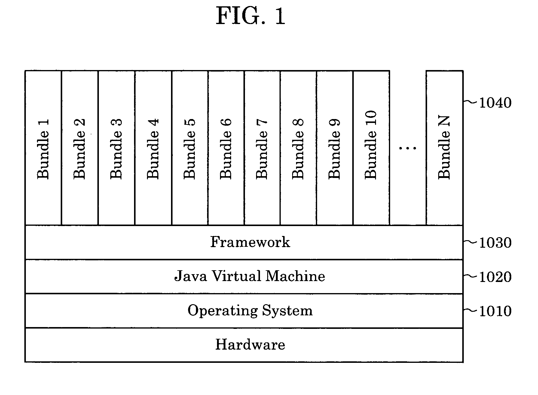
[0049]FIG. 1 illustrates the configuration of software running in the system according to an embodiment of the present invention. This configuration complies with the OSGi service platform written in “OSGi Service Platform Release 3” (Open Service Gateway Initiative, March, 2003).

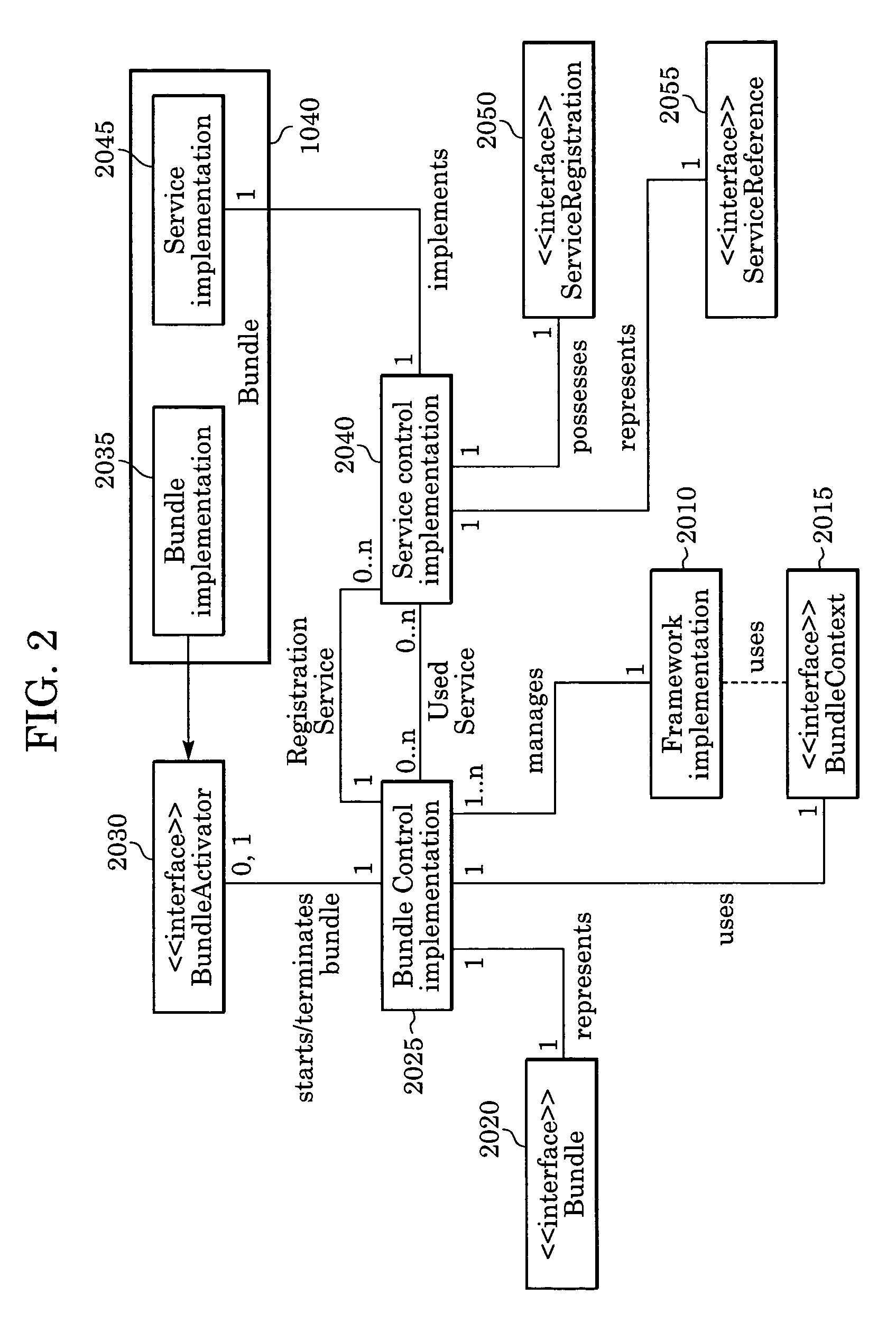
[0050] As shown in FIG. 1, the configuration includes an operating system 1010 for controlling hardware and software; a Java virtual machine 1020 running on the operating system 1010 to interpret and execute a byte code, which is an intermediate language generated by Java langua...

second embodiment

[0091] A second embodiment is described next.

[0092] The second embodiment including the software configuration is identical to the first embodiment except for the system shutdown process.

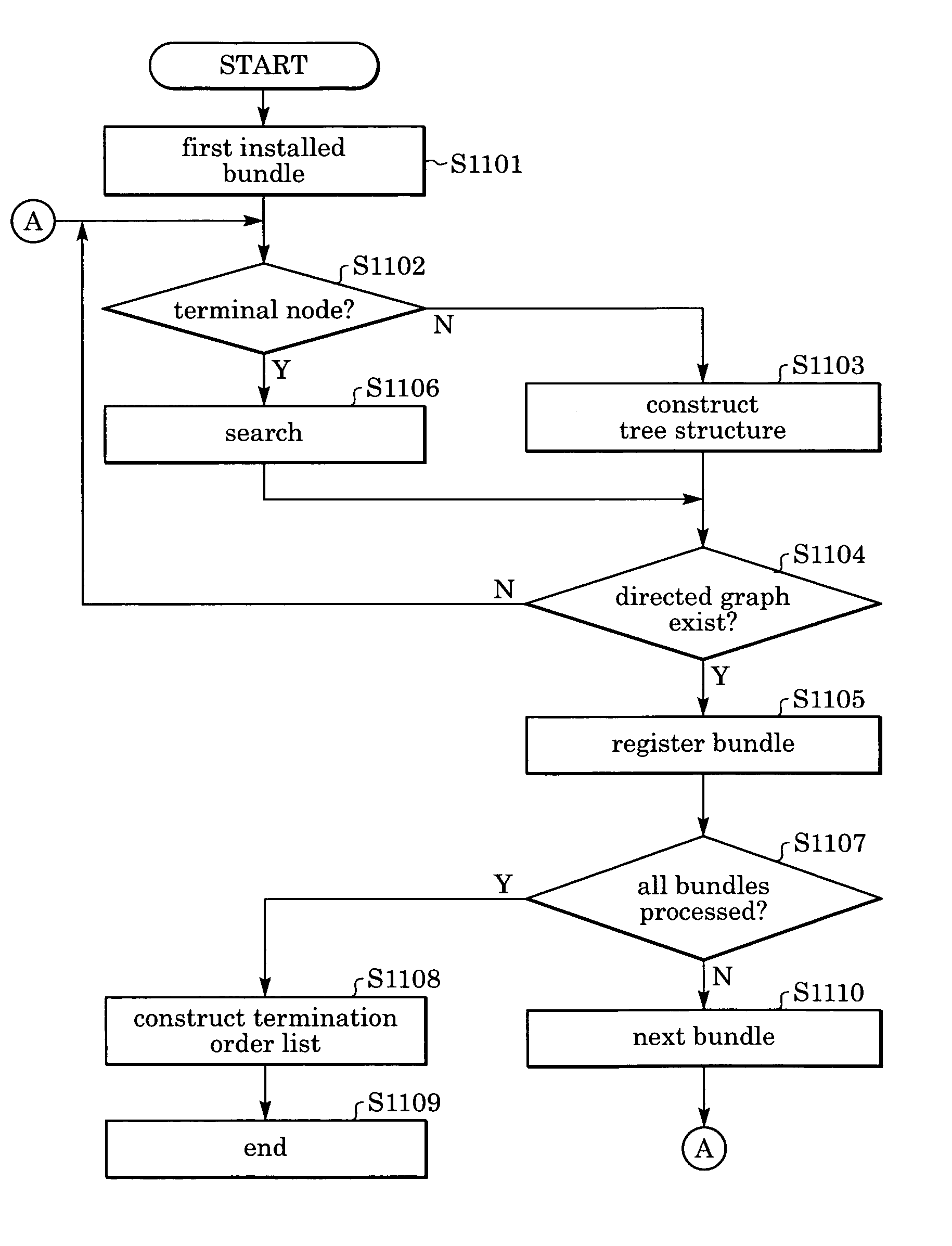
[0093] The system shutdown process is described with reference to a flow diagram in FIG. 9 and two examples in FIG. 10. In this embodiment, a dependency structure tree of program modules is derived from a dependency relationship among the program modules. By searching the tree structure, the termination order is defined such that a program module having a dependency on another program module is terminated first.

[0094] When attempting to shut down the system (step 910), the system invokes a “stop” method of the framework implementation class 2010 (step 915).

[0095] The framework implementation class 2010 invokes its own termination-order determination method (step 920).

[0096] The termination-order determination method acquires the reference service 3050 and the providing service 3060 from each bu...

third embodiment

[0106] A third embodiment of the present invention is described next. In the third embodiment, tree structures representing a dependency relationship among program modules are also derived from the dependency relationship among the program modules. By searching the tree structures, the termination order is then determined so that a program module depending on another program module is terminated first.

[0107] As in the second embodiment, a directed graph is generated from a statically determined reference relationship among services, and tree structures are then generated. That is, in this embodiment, a dependency relationship among program modules defined by the reference service 3050 and the providing service 3060 acquired by the termination-order determination method is also statically defined. A tree structure representing the dependency relationship among the program modules is derived from the defined dependency relationship.

[0108] In this embodiment, the termination order of...


PUM


Abstract

A software system terminates software modules in the reverse order of startup defined in a bundle start order list. Additionally, the software modules can be terminated in the order obtained by representing a static or dynamic reference relationship among the software modules as a tree structure and by searching the tree structure on a depth-first basis.

Description

BACKGROUND OF THE INVENTION [0001] 1. Field of the Invention [0002] The present invention relates to a software system including a plurality of program modules. [0003] 2. Description of the Related Art [0004] In known software systems including a plurality of program modules, some systems have start order control means that controls the order of starting the program modules at system start-up time (refer to, for example, Japanese Patent Laid-Open No. 2002-196939, Japanese Patent Laid-Open No. 2002-297403, Japanese Patent Laid-Open No. 2002-351677, and “OSGi Service Platform Release 3”, Open Service Gateway Initiative, March 2003). [0005] In general, the purpose of controlling the start order is to satisfy dependency relationships among program modules so that, when some program module uses a function provided by a different program module, the program module that provides a function is started first to avoid the failure of the start-up of the program module that uses the function. [...

Claims


Application Information

Patent Timeline
Patent Type & Authority Applications(United States)
IPC IPC(8): G06F9/45
CPCG06F9/485G06F9/445
Inventor USHIKU, TOYOHIKO
Owner CANON KK
Why Eureka
Try Eureka