Supercharged two-stroke engine with upper piston extensions

Inactive Publication Date: 2006-03-09
BESHORE CRAIG S
View PDF2 Cites 8 Cited by
  • Summary
  • Abstract
  • Description
  • Claims
  • Application Information

AI Technical Summary

Benefits of technology

[0011] In my presently pending U.S. patent application Ser. No. 10/804,351, I disclosed an advanced two-stroke cycle engine which avoids the aforementioned problems in the prior

Problems solved by technology

This results in some of the intake fuel-air mixture following the exhaust out of the exhaust port, thereby decreasing efficiency and increasing emissions.
Another shortcoming of prior art two-stroke engines arises because some of the engine's lubricating oil can pass to the exhaust port, thus producing emissions and often leaving deposits on the walls of the exhaust port, thus forming a hard carbon layer or “coking” which restricts the exhaust and causes other problems.
Yet another shortcoming of prior art two-stroke cycle engines involves the difficulty of bringing intake fuel-air mixture from the bottom of the engine cylinder to the top of the cylinder where the igniter is located.
Moving the small amount of fresh intake mixture undiluted by burnt gases to the igniter becomes very problematic.
Misfires are typical, resulting in irregular operation, and surging.
None of these various arrangements, however, have been wholly successful.
Yet another shortcoming of prior art two-stroke cycle engines involves the difficulty of lubricating the cylinder wall and piston.
Piston thrust against the cylinder wall then results in scuffing and premature wear.
This results in delivery of the charge at very limited pressure, limiting control of the scavenge process.
Mixing oil with the fuel or an expensive oiling system is also required, as are more expensive bearings that will survive on oil vapor only.
However, such systems are generally costly and often involve new problems.
None of these efforts, however, have been truly successful.

Method used


Image

  • Supercharged two-stroke engine with upper piston extensions
  • Supercharged two-stroke engine with upper piston extensions
  • Supercharged two-stroke engine with upper piston extensions

Examples


Embodiment Construction

[0044] The following discussion describes in detail one embodiment of the invention and several variations of that embodiment. This discussion should not be construed, however, as limiting the invention to those particular embodiments. Practitioners skilled in the art will recognize numerous other embodiments as well.

[0045] The invention is an apparatus 10 which can be useful in a two-stroke engine 11. The apparatus 10 of the invention is illustrated in FIGS. 29-31.

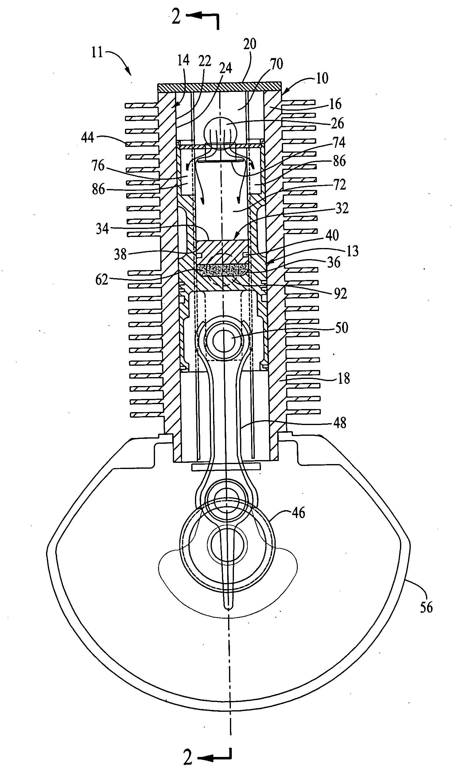
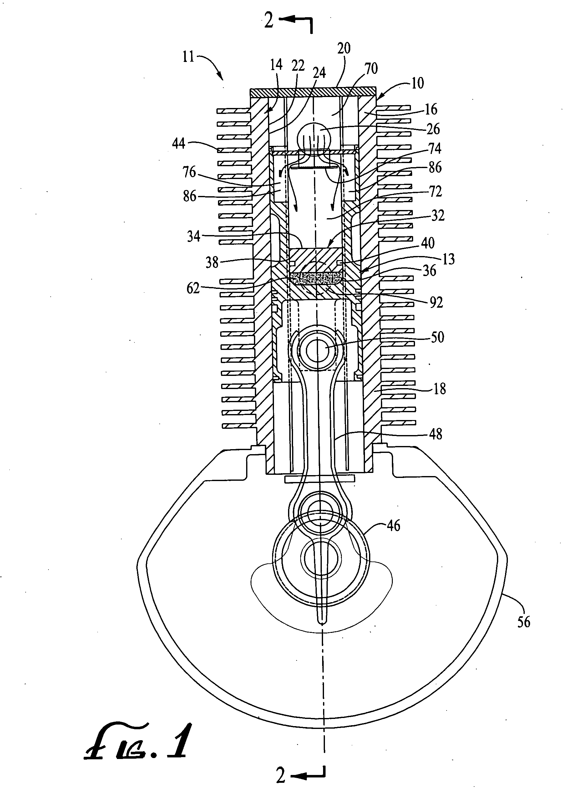
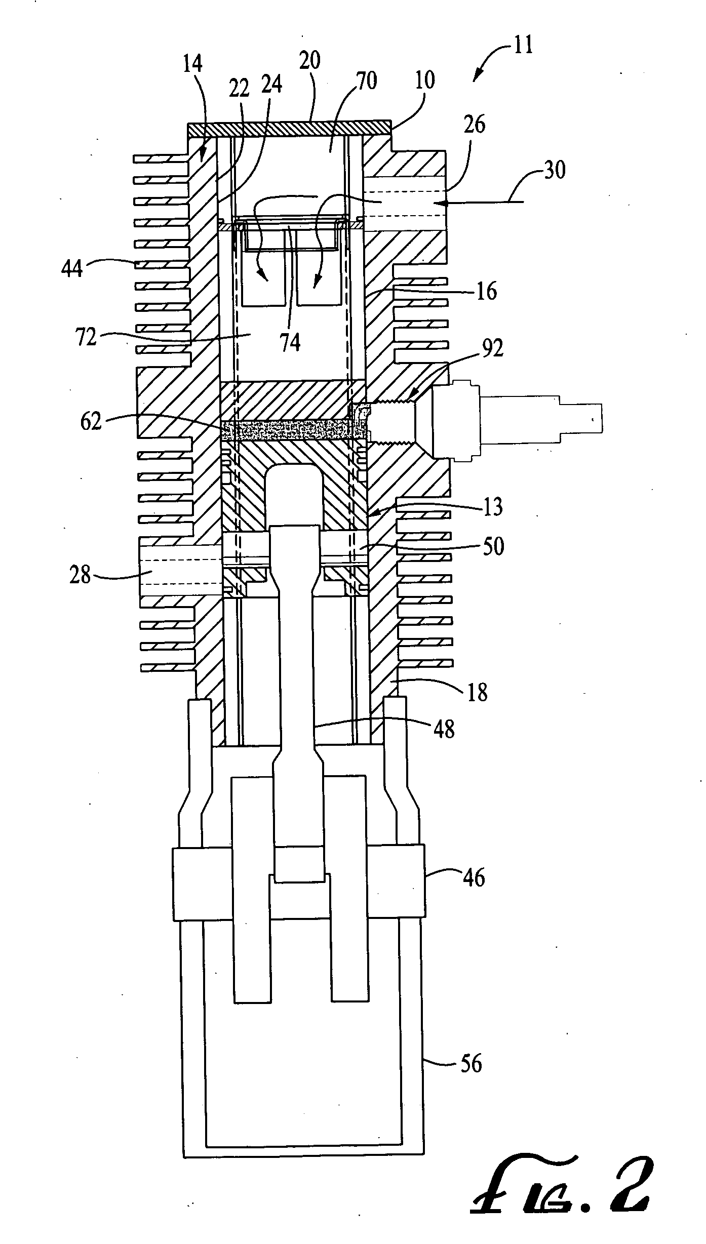
[0046] By way of background, the underlying concept of the invention is illustrated in FIGS. 1-28. In FIGS. 1-28, a basic apparatus 10 can be useful in both a two-stroke cycle engine 11 or in a pump 12. FIGS. 1-26 illustrate the apparatus 10 as used in a two-stroke cycle engine 11. FIGS. 27 and 28 illustrate the apparatus 10 as used in a pump 12.

[0047] The apparatus 10 comprises a uniquely configured piston 13 disposed within a uniquely configured piston cylinder 14. The piston cylinder 14 has a piston cylinder upper p...


PUM


Abstract

An apparatus useful in a two-stroke cycle engine or in a pump as a piston disposed within a piston cylinder. The piston cylinder has an intermediate piston cylinder head disposed transversely across the interior of the piston cylinder. The piston has at least one upright extension member extending upwardly from the lower portion. A piston top wall is disposed transversely to the piston cylinder side wall and is attached to the upper portion of the upright extension member of the piston. An upper chamber is defined above the piston top wall. An intermediate chamber is defined immediately below the piston top wall and a lower chamber is defined below the intermediate piston cylinder head. A tube connects the upper chamber with the lower chamber.

Description

RELATED APPLICATION [0001] The present application is a continuation-in-part of U.S. patent application Ser. No. 10 / 804,351 filed Mar. 17, 2004 entitled “Apparatus with Piston Having Upper Piston Extensions”; the contents of which are incorporated in this disclosure by reference in their entirety.FIELD OF THE INVENTION [0002] This invention relates generally to piston driven apparatuses, such as pumps and engines. In one specific embodiment, the invention relates to two-stroke cycle engines. BACKGROUND OF THE INVENTION [0003] Crank case scavenged, cylinder ported two-stroke cycle engines of the prior art are commonly used for a wide variety of light duty applications. Two-stroke cycle engines of the prior art, however, have several shortcomings. [0004] One shortcoming arises from the fact that prior art two-stroke cycle engines typically have intake and exhaust ports at about the same level. This results in some of the intake fuel-air mixture following the exhaust out of the exhaust...

Claims


Application Information

Patent Timeline
IPC IPC(8): F02B25/00F02B75/02F02B75/28F04B5/00F04B39/10F04B53/10
CPCF01L11/02F02B75/02F02B75/28F04B53/1037F02B2075/025F04B5/00F04B39/1073F02B75/30
Inventor BESHORE, CRAIG S.
Owner BESHORE CRAIG S
Why Eureka
Try Eureka