Laser-assisted placement of veiled composite material

a technology of veiled composite materials and lasers, which is applied in the direction of lamination, ancillary operations, chemical instruments and processes, etc., can solve the problems of non-uniform placement of fibers in composite materials, 100% of the resin veil being heated and subsequently melted, and insufficient precision of the resin veil to the tows to properly tack the thermoplastic resin veil

Inactive Publication Date: 2006-03-09
THE BOEING CO
View PDF23 Cites 108 Cited by
  • Summary
  • Abstract
  • Description
  • Claims
  • Application Information

AI Technical Summary

Benefits of technology

[0010] These and other objects and advantages of the present invention are achieved by providing a method of forming preform structures from fiber composite materials in an automated tape placement process. A resin veil of thermoplastic is introduced between layers of fiber tape and pulsed laser radiation is directed into a nip region of a compaction roller during formation of a composite preform structure to selectively heat discrete areas on the resin veil, to more precisely control tacking of the resin veil to the fiber tapes in predetermined locations.

Problems solved by technology

However, known hot gas torches used to provide heating of the tows and in heat bonding the resin veil to the tows are not precise enough to properly tack the thermoplastic resin veil to the tows, except at very low lay down rates.
Furthermore, the hot gas torches used in the known methods blow the fibers in the tows, which fibers are loosely held by the resin veil, thus causing the fibers to spread or bunch, resulting in non-uniform placement of the fibers in the composite material.
Additionally, as mentioned above, the hot gases are imprecise and produce non-selective heating of the materials, usually resulting in 100% of the resin veil being heated and subsequently melted.
This 100% heating of the resin veil causes problems, such as decreasing permeability by the non-selective melting of the thermoplastic resin, which blocks many potential migration paths during subsequent resin infusion.
This blocking of the migration paths inhibits rapid resin infusion and could result in composite materials having lower fiber volumes, thus resulting in reduced strength composite structures and higher infusion costs.
Therefore, gas torches are not a viable alternative to tack tows and resin veils, particularly in an automated tape placement apparatus and / or method.
The patent to Holmes et al., however, fails to disclose or teach the concept of modulating the laser diode array rapidly on and off to form discrete tack points.
Further-more, it does not address the use of a laser diode array to selectively heat discrete points on a resin veil to provide spot tacks between material layers at predetermined locations.
Nor does it address how spot tacking could be made between layers during automated tape placement of a preform structure that is subsequently used in a resin infusion process.

Method used


Image

  • Laser-assisted placement of veiled composite material
  • Laser-assisted placement of veiled composite material

Examples


Embodiment Construction

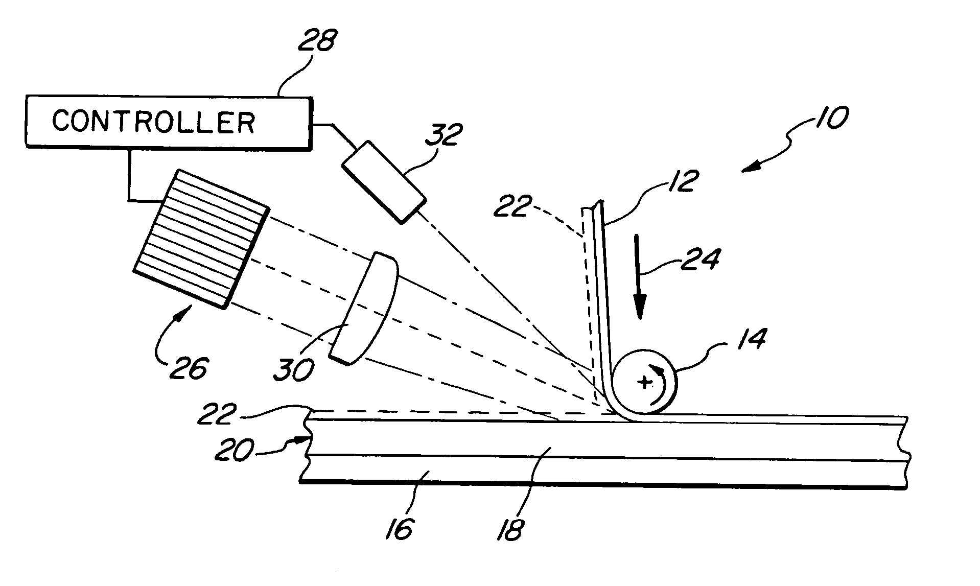
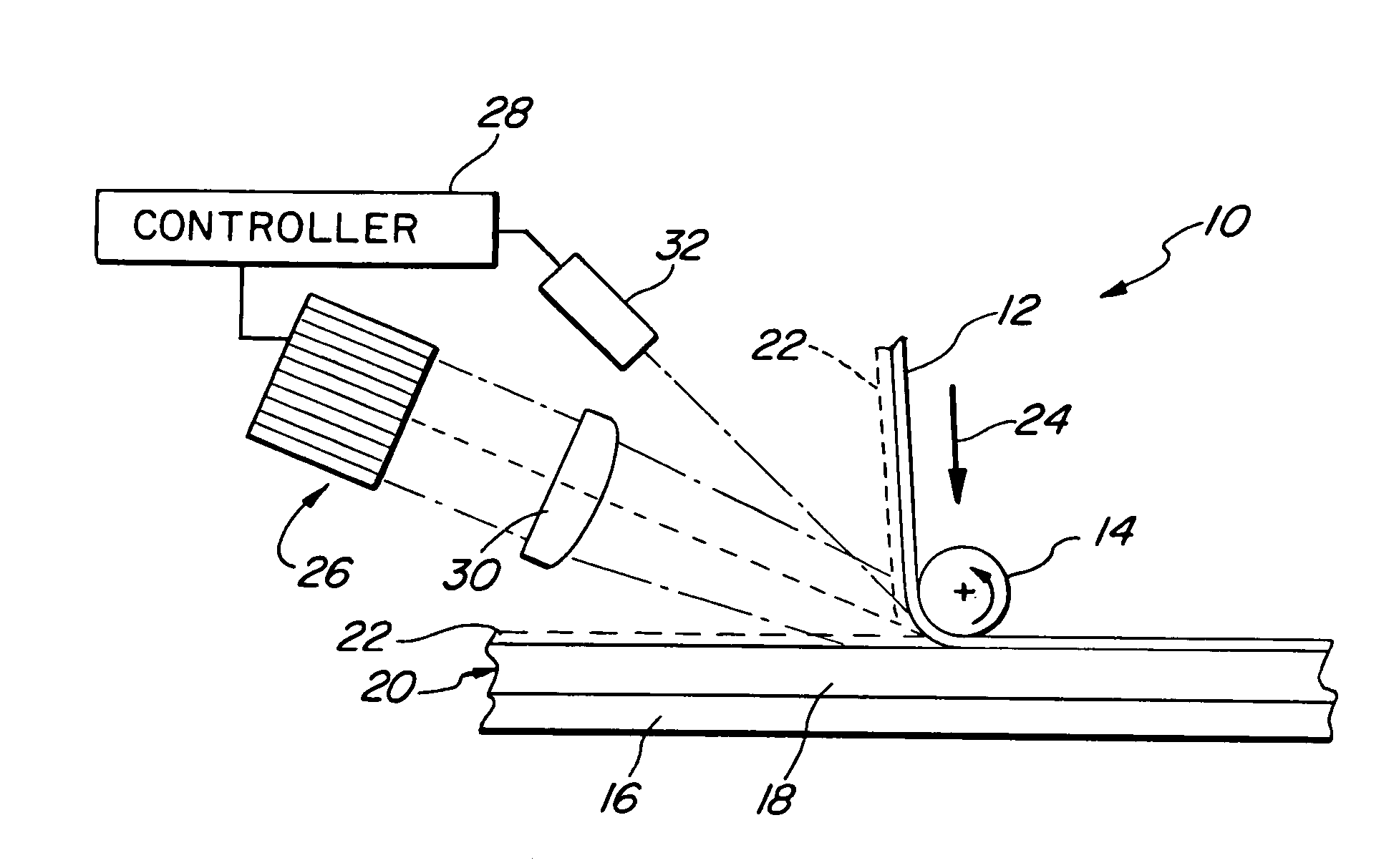
[0013] The following description is provided to enable any person skilled in the art to make and use the invention and sets forth the best modes contemplated by the inventors of carrying out their invention. Various modifications, however, will remain readily apparent to those skilled in the art, since the generic principles of the present invention have been defined herein specifically to describe an improved method of automated fabrication of preform structures from composite materials utilizing a permeable spider-web-like resin veil of thermoplastic material to hold together fiber tape or tows, such as carbon-fiber tows. The resin veil is formed as an interlayer made of spunbonded, spunlaced or mesh fabric thermoplastic fibers and is discretely heated at selected points by pulsed laser radiation from one or more lasers. The lasers are preferably diode lasers supported in one or more arrays, in any desired configuration and manner, for example in a head on an automated tape placem...


PUM

PropertyMeasurementUnit
areasaaaaaaaaaa
areaaaaaaaaaaa
sizeaaaaaaaaaa

Abstract

A method of forming preform structures from fiber composite materials in an automated tape placement process, for subsequent resin infusion and heating. Pulsed laser radiation is directed into a nip region of a compaction roller during formation of a composite preform structure to selectively heat discrete areas on a resin veil of thermoplastic to an incoming fiber tape material and a surface of a substrate, to more precisely control tacking of the resin veil of thermoplastic to the fiber tape and the surface of a substrate in predetermined locations.

Description

BACKGROUND OF THE INVENTION [0001] 1. Field of the Invention [0002] This invention generally relates to the manufacture of composite materials and, more particularly, to a process of automated tape placement to manufacture preform structures from composite materials utilizing a resin veil that is selectively spot tacked to fiber tapes or tows, by the use of pulsed laser radiation. [0003] 2. Description of the Prior Art [0004] It is known to form high-performance composite materials built of alternating layers of unidirectional reinforcing fibers to form high strength and lightweight materials for use in aerospace and other industries. Such composite materials may be continuously and more affordably manufactured using automated layup of the composite materials. The final composite materials may be produced using what are referred to as prepregs or preforms. When using preforms, continuous and increased speed of fabricating machines and reduced cost of fabrication is obtained if the a...

Claims


Application Information

Patent Timeline
Patent Type & Authority Applications(United States)
IPC IPC(8): B29C65/00B32B37/00
CPCB29C65/1632B29C66/934B29C66/939B29C70/386B29K2105/06B29B11/16B29C66/8362B29C65/1658B29C65/1664B29C65/1674B29C66/9121B29C66/9131B29C66/91641B29C66/919B29C66/45B29C66/7212B29C66/7392B29C66/1122B29C70/388B29K2307/04
Inventor EVANS, RICHARD B.LAWTON, STANLEY A.
Owner THE BOEING CO
Why Eureka
Try Eureka