Dual feed laser welding system

a laser welding and dual-feed technology, applied in the field of welding, can solve the problems of significant operating expense and time out of service, stress loading of lpc/hpc components, and degradation of lpc/hpc components over tim

Inactive Publication Date: 2006-03-09
HONEYWELL INT INC
View PDF47 Cites 78 Cited by
  • Summary
  • Abstract
  • Description
  • Claims
  • Application Information

AI Technical Summary

Problems solved by technology

The LPC/HPC components are subjected to stress loadings during turbine engine operation, and also are impacted by foreign objects such as sand, dirt, and other such debris.
The LPC/HPC components can degrade over time due to wear, erosion and foreign object damage.
Sometimes LPC/HPC components are degraded to a point at which they must be repaired or replaced, which that can result in significant operating expense and time out of service.
The option of throwing out worn engine components such as turbine blades and replacing them with new ones is not an attractive alternative.
The blades are extremely expensive due to costly material and manufacturing process.
A high pressure turbine blade made of superalloy can be quite costly to replace, and a single stage in a gas turbine engine may contai

Method used


Image

  • Dual feed laser welding system
  • Dual feed laser welding system
  • Dual feed laser welding system

Examples


Embodiment Construction

[0022] The following detailed description of the invention is merely exemplary in nature and is not intended to limit the invention or the application and uses of the invention. Furthermore, there is no intention to be bound by any theory presented in the preceding background of the invention or the following detailed description of the invention. Reference will now be made in detail to exemplary embodiments of the invention, examples of which are illustrated in the accompanying drawings. Wherever possible, the same reference numbers will be used throughout the drawings to refer to the same or like parts.

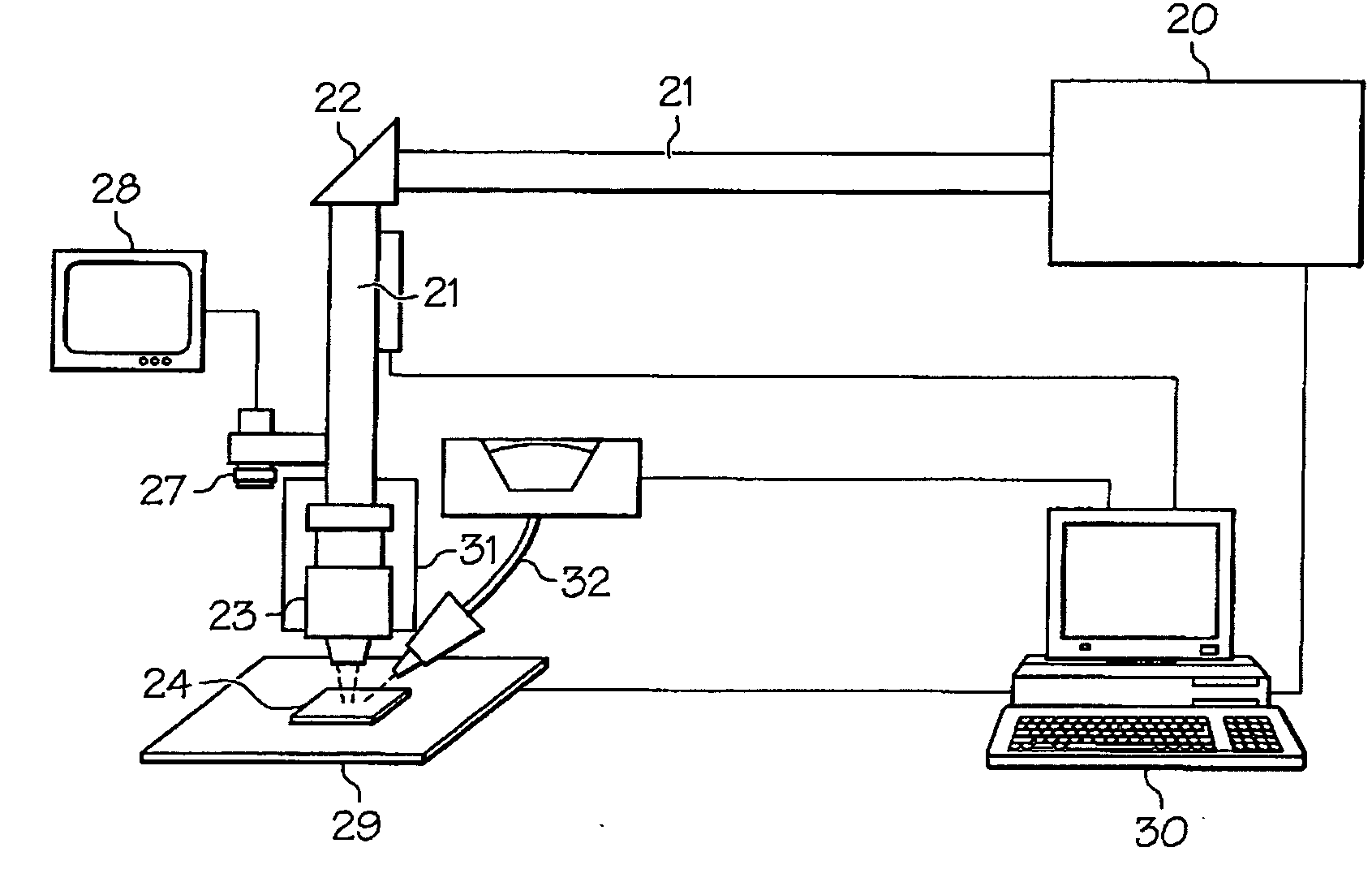
[0023] Referring now to FIG. 1 there is shown a schematic diagram of a general apparatus for laser generation and control that may be used in the dual-feed laser welding system according to an embodiment of this invention. Laser generating means 20 generates a laser used in the welding system. A laser is directed through beam guide 21, through mirror 22, and through focus lens 23. ...


PUM

PropertyMeasurementUnit
Poweraaaaaaaaaa
Mesh sizeaaaaaaaaaa
Mesh sizeaaaaaaaaaa

Abstract

The present invention provides an apparatus for automated laser welding repairs. The apparatus is adapted for use with components of gas turbine engines such as compressor and turbine airfoils and blisks. The apparatus comprises a dual means of providing filler material. The filler material may be provided through a wire feeder. Optionally, the filler material may be provided through a powder feeder.

Description

FIELD OF THE INVENTION [0001] The present invention relates to welding. More particularly the invention relates to automated laser welding and the material feeding systems by wire and powder in automated welding systems. BACKGROUND OF THE INVENTION [0002] Turbine engines are used as the primary power source for many types of aircrafts. The engines are also auxiliary power sources that drive air compressors, hydraulic pumps, and industrial gas turbine (IGT) power generation. Further, the power from turbine engines is used for stationary power supplies such as backup electrical generators for hospitals and the like. [0003] Most turbine engines generally follow the same basic power generation procedure. Compressed air generated by axial and / or radial compressors is mixed with fuel and burned, and the expanding hot combustion gases are directed against stationary turbine vanes in the engine. The vanes turn the high velocity gas flow partially sideways to impinge on the turbine blades mo...

Claims


Application Information

Patent Timeline
IPC IPC(8): B23K26/20
CPCB23K26/03B23K26/032B23K26/0853B23K26/123B23K2201/001B23K35/0283B23K26/3213B23K26/322B23K26/345B23K35/0244B23K35/0261B23K26/3206B23K26/32B23K26/342B23K2101/001B23K2103/08B23K2103/26B23K2103/50
Inventor CAHOON, CHRISTOPHER L.DOWDING, RANDALL E.SANKARANARAYANAN, SRIKANTH
Owner HONEYWELL INT INC
Why Eureka
Try Eureka