Vehicle suspension system

Inactive Publication Date: 2006-03-09
HONDA MOTOR CO LTD
View PDF7 Cites 8 Cited by
  • Summary
  • Abstract
  • Description
  • Claims
  • Application Information

AI Technical Summary

Benefits of technology

[0007] The present invention has been achieved in view of the above-mentioned circumstances. One aspect of the present invention is to redu

Problems solved by technology

However, in the case where the abutment surface is inclined with respect to the axis of the bump stopper for reasons that are provided below, th

Method used


Image

  • Vehicle suspension system
  • Vehicle suspension system
  • Vehicle suspension system

Examples


Embodiment Construction

[0019] FIGS. 1 to 4 illustrate a preferred embodiment of the present invention.

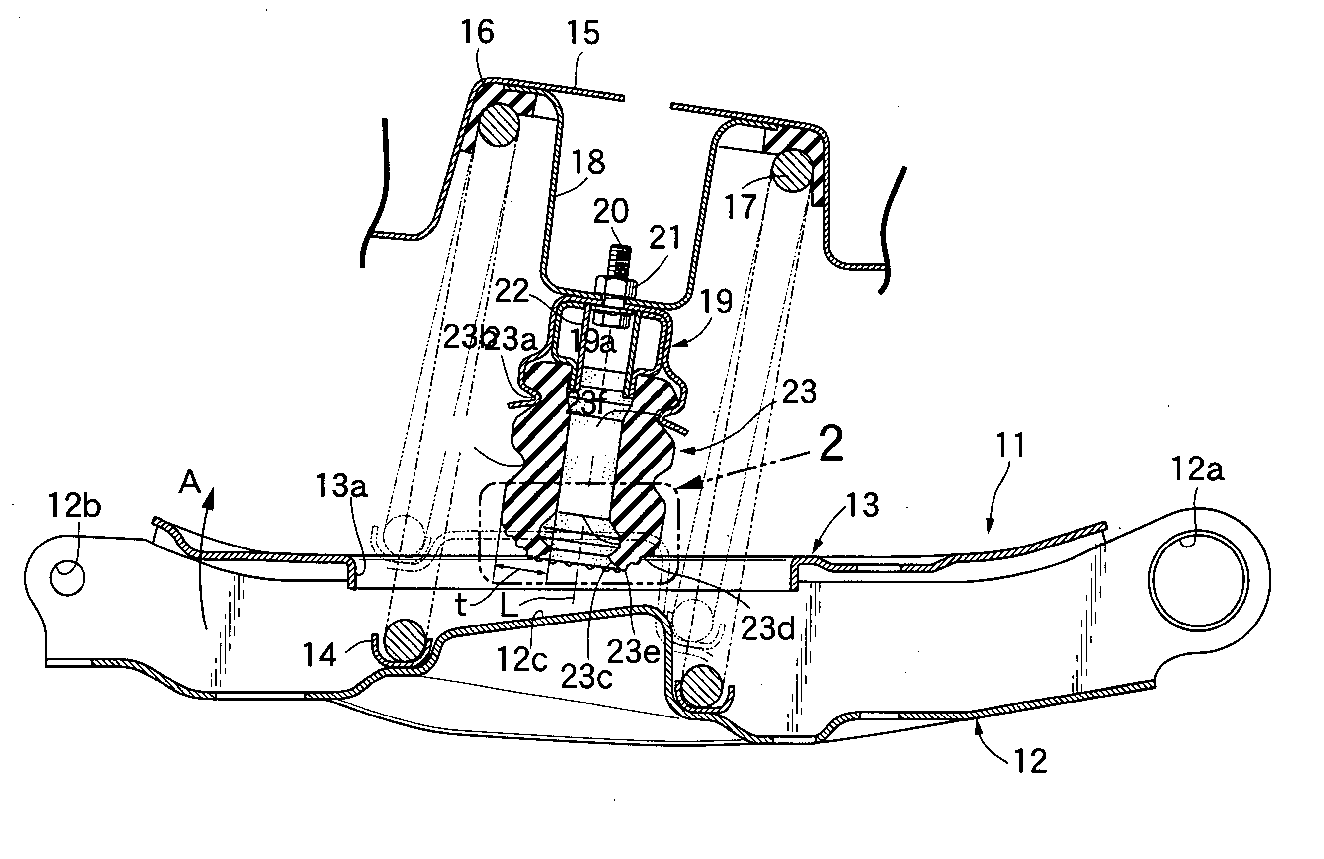
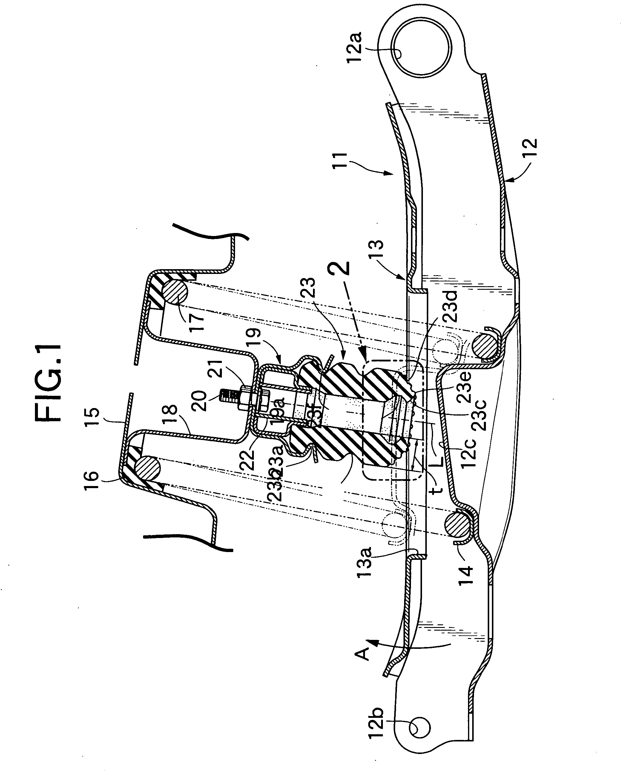
[0020] As shown in FIG. 1, a lower arm 11 of a vehicle suspension system is illustrated which has a cationic coating applied to a press-formed steel plate. The lower arm 11 includes a lower member 12, that is U-shaped in section and has an opened top surface, and an upper member 13 connected to the lower member 12 which covers the opening of the lower member's top surface. The lower member 12 includes, at an inner end in a widthwise direction of the vehicle, an inner pivotal support part 12a pivotally supported on the body of the vehicle via a rubber bush joint; and, at an outer end in the widthwise direction of the vehicle, an outer pivotal support part 12b pivotally supported on a knuckle via a ball joint. A circular abutment surface 12c protrudes upward at a central part of the lower member 12. An annular lower spring seat 14 is disposed around the abutment surface 12c. A circular opening 13a is forme...


PUM


Abstract

A vehicle suspension system connects a swing member to a vehicle body. The vehicle suspension system includes a bump stopper, which is provided on one of the swing member and the vehicle body and includes an axis, a substantially cylindrical tip end which abuts an abutment surface provided on the other one of the swing member and the vehicle body, and an apex formed at the tip end. Abutment is initiated, in a circumferential direction of the tip end, in a state wherein the abutment surface inclines relative to the axis of the bump stopper. The apex at the tip end of the bump stopper first abuts the abutment surface and is located at an intermediate portion of the bump stopper in a direction of a wall thickness (t) of the bump stopper. A plurality of projections may also be formed on the tip end of the bump stopper.

Description

[0001] The present invention is based upon Japanese priority application No. 2004-258117, which is hereby incorporated in its entirety herein by reference. BACKGROUND OF THE INVENTION [0002] 1. Field of the Invention [0003] The present invention relates to a vehicle suspension system which restricts a maximum bump amount of a vehicle body by connecting a swing member, which rotatably supports a wheel and swings up and down, to a vehicle body via a suspension spring. A substantially cylindrical tip end of a bump stopper provided in one of the swing member and the vehicle body abuts an abutment surface provided in the other one of the swing member and the vehicle body. [0004] 2. Description of the Related Art [0005] Japanese Patent Application Laid-open No. 9-272317 discloses a vehicle suspension system which supports a knuckle that rotatably supports a wheel on a vehicle body via a suspension arm that is movable in up and down directions. The suspension system includes a bump stopper...

Claims


Application Information

Patent Timeline
IPC IPC(8): B60G9/00B60G11/54
CPCF16F2230/007F16F9/58
Inventor OKAMOTO, KIMIOSUZUKI, KAZUTAKAINABA, SHIGENORI
Owner HONDA MOTOR CO LTD
Why Eureka
Try Eureka