Display and color cathode ray tube

a cathode ray tube and display apparatus technology, applied in the field of display apparatus and color cathode ray tube, can solve the problems of pigment exfoliation, low luminance of display apparatus, pigment exfoliation, etc., and achieve the effect of improving contrast, reducing external light reflectance, and improving contras

Inactive Publication Date: 2006-03-09
SONY CORP
View PDF6 Cites 34 Cited by
  • Summary
  • Abstract
  • Description
  • Claims
  • Application Information

AI Technical Summary

Benefits of technology

[0031] In this case, when employing the panel glass having light transmissivity of 55% to 20% when a wavelength is 546 nm and a plate thickness is 20 mm, the external-light reflectance can further be reduced and further improvement in contrast is obtained. If an antireflective film is formed on the other surface, that is, on the outside surface of the panel glass, still further improvement in contrast can be obtained.
[0032] According to the color cathode-ray tube of the present invention, by employing the panel glass having light transmissivity of 55% to 20% when a wavelength is 546 nm and a plate thickness is 20 mm, the external-light reflectance can greatly be reduced. In addition, by including the fluorescent screen which has the color-filter layer and phosphor layer and in which at least the phosphor layer is formed by the transfer method, the luminance can be improved, or a decrease in luminance can be suppressed to the minimum. Accordingly, a picture display with excellent contrast in high luminance can be attained.
[0033] When either the intermediate film or the metal-back layer on phosphor layer, or both of them are formed by the transfer method, the planarized reflecting surface can be formed on the inside surface of the metal-back layer, which makes the reflective efficiency in the metal-back layer further improved and enables the improvement in luminance to be obtained.
[0034] When including the fluorescent screen in which the metal-back layer is directly formed on the phosphor layer by transfer method, the planarized reflective surface can also be formed on the inside surface of the metal-back layer, which makes the reflective efficiency further improved and enables the improvement in luminance to be obtained.
[0035] When the phosphor layer of the fluorescent screen is formed of the photosensitive phosphor layer containing no Cr, the luminance after the baking process becomes improved than in related art. Further, if a film thickness of this phosphor layer is set to 10 μm to 15 μm, the optimum luminance can be obtained. Thus, by including the fluorescent screen with the color-filter layer and such phosphor layer, the luminance can be improved. Therefore, it is possible to attain the picture display with excellent contrast in high luminance.
[0036] In this case, when employing the panel glass having light transmissivity of 55% to 20% when a wavelength is 546 nm and a plate thickness is 20 mm, the external-light reflectance can further be reduced and further improvement in luminance is obtained. If the antireflective film is formed on the other surface, that is, on the outside surface of the panel glass, still further improvement in contrast can be obtained.

Problems solved by technology

However, the use of the panel glass with low transmissivity will lower the luminance of a display apparatus.
Moreover, the use of the phosphor with pigment makes the pigment absorb the luminous light from the phosphor with the result that the luminance decreases, and also makes the pigment exfoliate during a manufacturing process of display apparatus, which have been considered as problems.
Particularly, when forming a red filter layer, because ferric oxide and cadmium sulfoselenide each used as red pigment have a characteristic of absorbing and not passing ultraviolet rays during the exposure, it is difficult to apply the internal exposure method in which a striped filter layer is formed by performing exposure from the side of the filter-applied film surface.
With this specification, the luminance is improved indeed, however, blackness of the tube surface (what is called tube-surface reflectance) determining a black portion of a picture is not improved, so that the blackness is insufficient to make a feeling of contrast in the picture weakened.

Method used


Image

  • Display and color cathode ray tube
  • Display and color cathode ray tube
  • Display and color cathode ray tube

Examples


Embodiment Construction

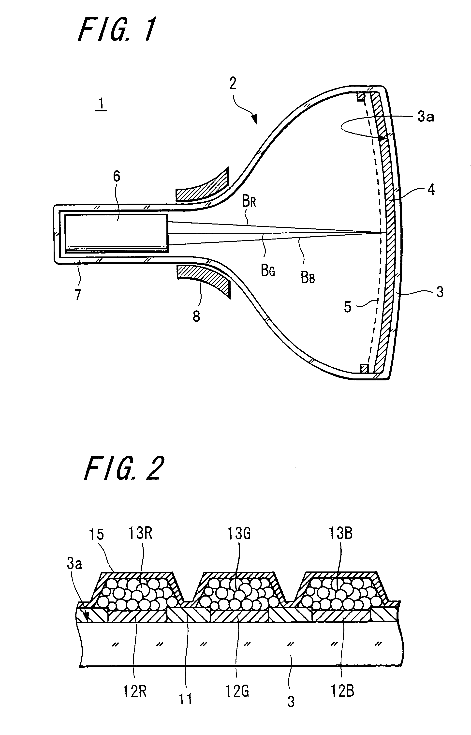
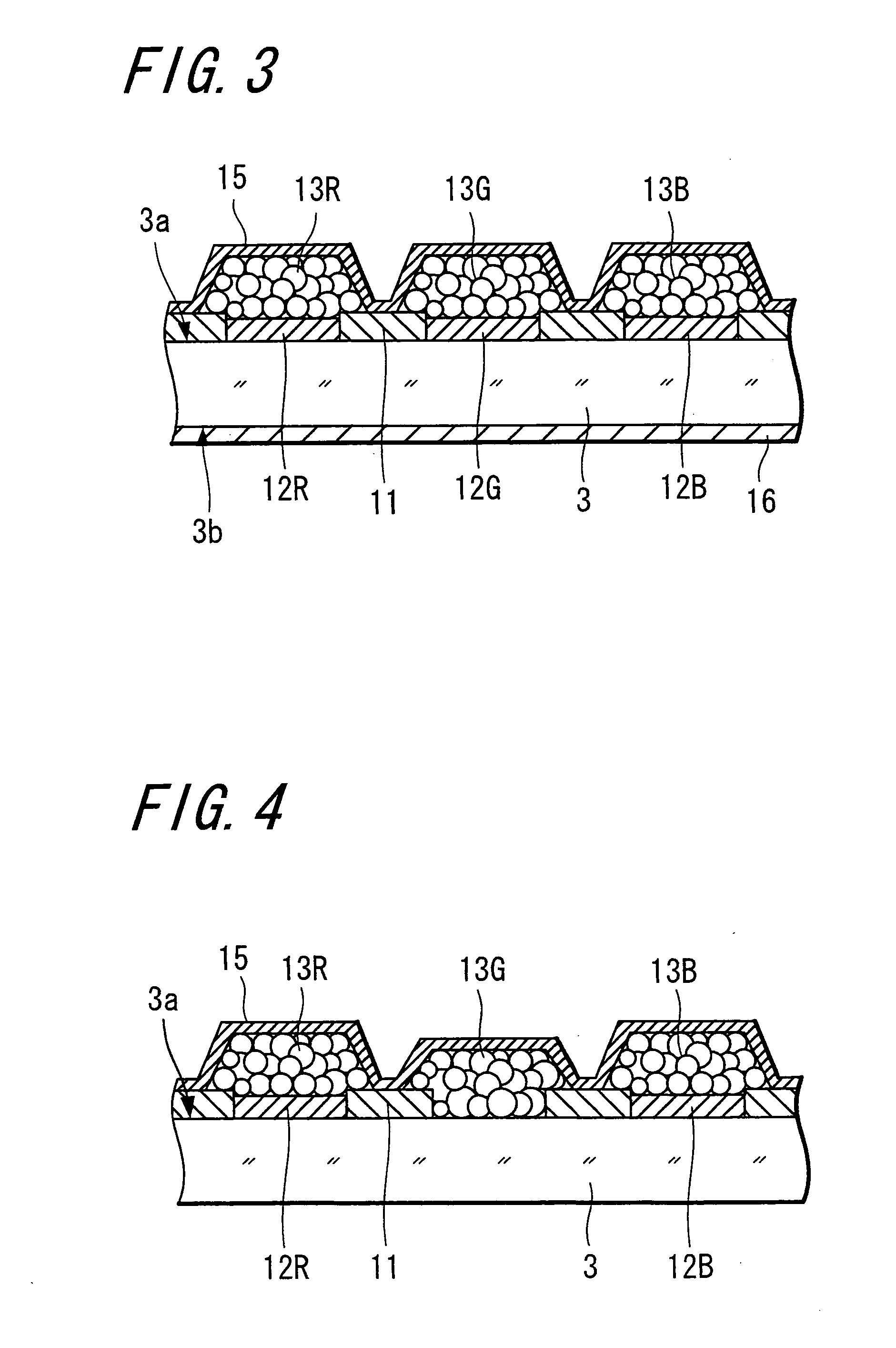
[0052] The first characteristic of the present invention is a structure in which a fluorescent screen with a color-filter layer formed by a transfer method is combined with a panel glass having low transmissivity to improve the contrast and the luminance.

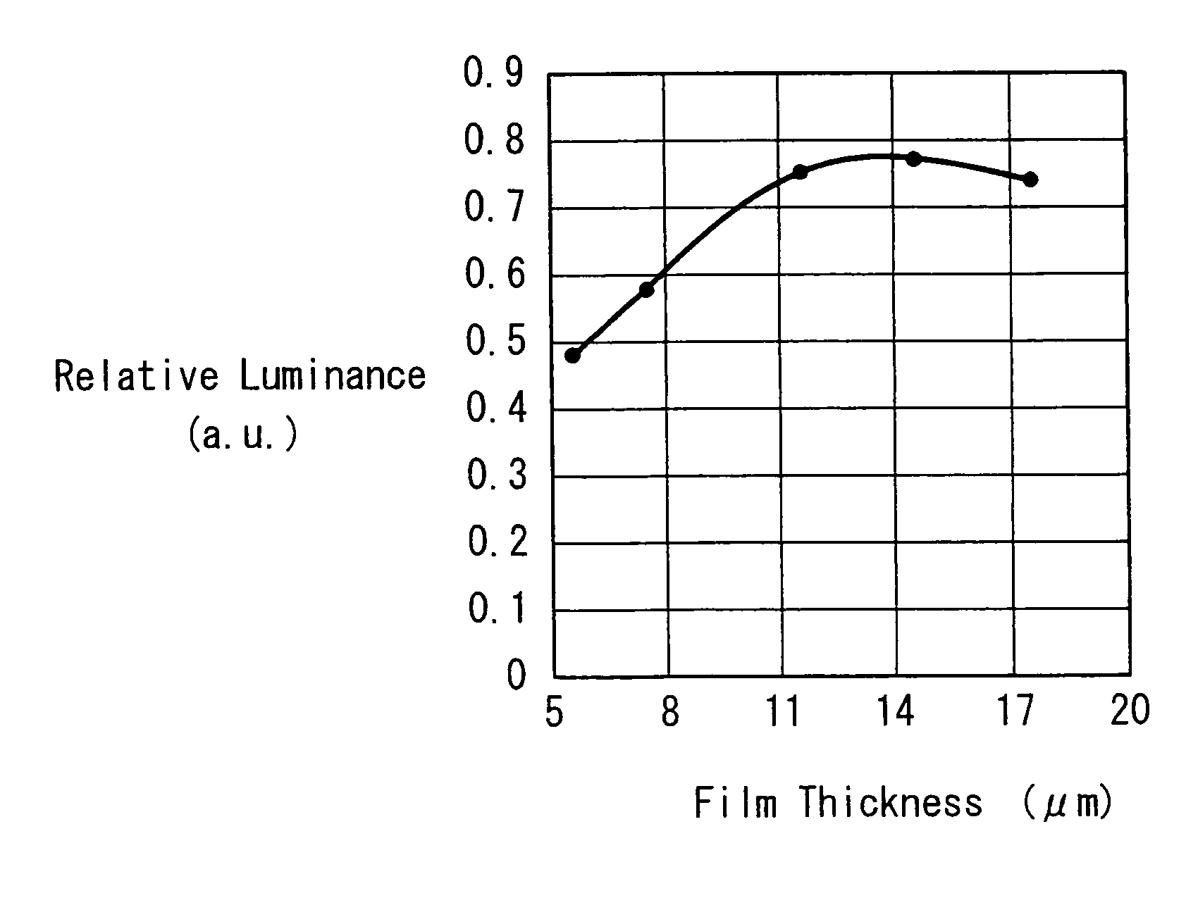
[0053] The second characteristic of the present invention is a structure in which a film thickness of a phosphor layer in the fluorescent screen with the color filter is optimized and a photosensitive phosphor layer containing no Cr is employed to improve the luminance and the contrast. Further, the surface of a metal-back layer having high planarity and high reflectance (for example, aluminum film) is fabricated by forming at least either an intermediate film or the metal-back layer by the transfer method to improve the luminance.

[0054] First, to make the present invention easily understood, a relation between the luminance and the brightness perceived by human beings as well as contrast ratio will be described. The contrast rati...


PUM


Abstract

The present invention aims at compatibility between the improvement in luminance or suppression of deterioration in luminance and the improvement in contrast with respect to a display apparatus and a color cathode-ray tube. Each of the display apparatus and the color cathode-ray tube according to the present invention includes: a fluorescent screen having a color-filter layer and a phosphor layer, which is formed inside a panel glass having light transmissivity of 55% to 20% when a wavelength is 546 nm and a plate thickness is 20 mm and in which at least the phosphor layer is formed by the transfer method.

Description

TECHNICAL FIELD [0001] The present invention relates to a display apparatus and a color cathode-ray tube including a fluorescent screen in which a phosphor layer is combined with a color filter. BACKGROUND ART [0002] It has heretofore been intended to improve contrast of a picture in a display apparatus including, for example, a color cathode-ray tube. To improve the contrast, there are methods, one of which is to increase luminance and the other of which is to reduce reflectance of external light on a tube surface. Thus, there has been proposed a method for improving the contrast by lowering the external-light reflectance using a panel glass with low transmissivity which forms the fluorescent screen. Alternatively, there has been proposed another method for improving the contrast using what is called a “phosphor with pigment” as the phosphor forming the fluorescent screen, in which pigment having the same color as a luminous color of the phosphor is stuck on the surface of phosphor...

Claims


Application Information

Patent Timeline
Patent Type & Authority Applications(United States)
IPC IPC(8): G09G3/00H01J9/227H01J29/28H01J29/32H01J29/89
CPCH01J9/227H01J29/898H01J29/32H01J9/20
Inventor KUSUNOKI, TSUNEOOHNO, KATSUTOSHIFUJITA, KOJIIGARASHI, TAKAHIRO
Owner SONY CORP
Why Eureka
Try Eureka