Liquid crystal display

a liquid crystal display and display technology, applied in non-linear optics, instruments, optics, etc., can solve the problems of narrow color reproduction range, inability to improve color purity, inferior color reproduction ability compared to crt, etc., to achieve wide color reproduction range, improve ntsc ratio, and improve color purity of illumination light

Inactive Publication Date: 2006-03-09
SONY CORP
View PDF2 Cites 24 Cited by
  • Summary
  • Abstract
  • Description
  • Claims
  • Application Information

AI Technical Summary

Benefits of technology

[0024] According to the liquid crystal display of the embodiment of the present invention, only the light in the specific wavelength regions among the light generated from the light source is selectively guided to the liquid crystal panel by using the light selective transmission filter or the light selective reflection filter having wavelength selective characteristics corresponding to spectral characteristics of the light source. Therefore, the color purity of illumination light can be improved. Thereby, the NTSC ratio can be improved, and the wide color reproduction range can be secured.
[0025] In particular, when the light selective transmission filter, in which light transmittance in the red region, the green region, and the blue region is 80% or more, and the rest of the red, green and blue region has wavelength regions whose light transmittance is 10% or less adjacent to the green region is used, the light selective transmission filter is better adapted to the light source generating light having a intensity peaks at least in one of the red region, the green region, and the blue region, and the color purity of the illumination light can be sufficiently improved.

Problems solved by technology

However, in the traditional transmissive liquid crystal display as above, there has been a disadvantage that color reproduction ability is inferior compared to in the CRT.
As a result, the color purity is not able to be improved, and the color reproduction range is narrow.
As above, in the traditional technique, in which color separation is performed for light emitted from the light source by only the color filter having transmission characteristics with a wide wavelength band, it has been difficult to obtain a liquid crystal display having a wide color reproduction range.

Method used


Image

  • Liquid crystal display
  • Liquid crystal display
  • Liquid crystal display

Examples


first embodiment

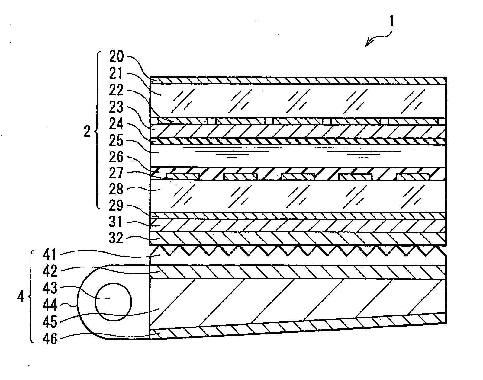
[0046]FIG. 4 shows a cross sectional structure of a liquid crystal display according to a first embodiment of the present invention. A liquid crystal display 1 is used as a transmissive liquid crystal display and an active matrix liquid crystal display. The liquid crystal display 1 includes a liquid crystal panel 2, a luminaire 4 including a light source arranged behind the liquid crystal panel 2, and a diffusion sheet 31 and a light selective transmission filter 32 arranged between the liquid crystal panel 2 and the luminaire 4.

[0047] The liquid crystal panel 2 has a laminated structure having a liquid crystal layer 25 between a glass substrate 21 on the observer side and a glass substrate 28 on the luminaire 4 side. Specifically, the liquid crystal panel 2 has a polarizing plate 20, the glass substrate 21, a color filter 22, a transparent electrode 23, an orientation film 24, the liquid crystal layer 25, an orientation film 26, a transparent pixel electrode 27, the glass substrat...

modification 1

[Modification 1]

[0092] In this modification, the light selective transmission filter is arranged on the surface of the cold-cathode fluorescent lamp 43 as a light source in the first embodiment.

[0093]FIG. 10 shows a cross sectional structure of a liquid crystal display according to this modification. A liquid crystal display 11 of this modification includes the liquid crystal panel 2, the luminaire 4 arranged behind the liquid crystal panel 2, and the diffusion sheet 31 arranged therebetween. The point different from the liquid crystal display 1 in the first embodiment is that a light selective transmission filter 33 is arranged on the surface of the cold-cathode fluorescent lamp 43 as a light source as described above. The light selective transmission filter 33 is not always directly arranged on the surface of the cold-cathode fluorescent lamp 43, but other layer may be sandwiched inbetween. Other respective components are similar to of the first embodiment, and therefore descript...

modification 2

[Modification 2]

[0097] This modification relates to a so-called underlay luminaire, in which the cold-cathode fluorescent lamp 43 as a light source is arranged directly under the liquid crystal panel 2 in the first embodiment.

[0098]FIG. 11 shows a cross sectional structure of a liquid crystal display according to this modification. A liquid crystal display 12 of this modification includes the liquid crystal panel 2, the luminaire 4 arranged behind the liquid crystal panel 2, the diffusion sheet 31 and the light selective transmission filter 32, which are arranged between the liquid crystal panel 2 and the luminaire 4. The point different from the liquid crystal display 1 in the first embodiment is that the luminaire 4 has a underlay configuration. That is, the luminaire 4 has a structure in which a plurality of cold-cathode fluorescent lamps 43 as a light source (in this modification, the case, in which four cold-cathode fluorescent lamps 43 are arranged is shown) and the lamp refl...


PUM

PropertyMeasurementUnit
light transmittanceaaaaaaaaaa
light reflectanceaaaaaaaaaa

Abstract

A liquid crystal display having a wide color reproduction range is provided. A liquid crystal display includes a liquid crystal panel driven based on image signals, a light source emitting light for illuminating the liquid crystal panel, and a light selective transmission filter, which has wavelength selective transmission characteristics corresponding to spectral characteristics of the light source, selectively transmits light generated from the light source in the specific wavelength regions based on the wavelength selective transmission characteristics, and guides the transmitted light to the liquid crystal panel.

Description

CROSS REFERENCES TO RELATED APPLICATIONS [0001] The present invention contains subject matter related to Japanese Patent Application JP 2004-258831 filed in the Japanese Patent Office on Sep. 6, 2005, the entire contents of which being incorporated herein by reference. BACKGROUND OF THE INVENTION [0002] 1. Field of the Invention [0003] The present invention relates to a liquid crystal display displaying images by utilizing a light source arranged behind a liquid crystal panel. [0004] 2. Description of the Related Art [0005] In these years, the cathode ray tube (CRT), which has been traditionally a mainstream of displays has been replaced by the liquid crystal display, since the liquid crystal display has advantages such as low power consumption, space-saving feature, and low cost. [0006] There are several types of liquid crystal displays when categorized by, for example, illumination methods in displaying images. As a representative example, a transmissive liquid crystal display, wh...

Claims


Application Information

Patent Timeline
Patent Type & Authority Applications(United States)
IPC IPC(8): G02F1/1335
CPCG02F1/133514G02F2001/133521G02F1/133621G02F1/133521
Inventor KIRITA, SHINAOHSAKO, JUNICHIKAWASHIMA, TOSHITAKAKAKINUMA, MASAYASUHAGA, SHUICHI
Owner SONY CORP
Why Eureka
Try Eureka