Free electron laser, and associated components and methods

a free electron laser and laser technology, applied in the field of free electron lasers, can solve the problems of source and detector, lack of intensity, frequency-tuning ability and/or stability, and inapplicability,

Active Publication Date: 2006-03-09
QUALCOMM INC
View PDF4 Cites 91 Cited by
  • Summary
  • Abstract
  • Description
  • Claims
  • Application Information

AI Technical Summary

Benefits of technology

[0006] In one embodiment, a free electron laser (“FEL”) employing the Smith-Purcell effect is disclosed. The FEL includes a diffraction grating element that has...

Problems solved by technology

In the FIR gap, various sources and detectors exist; but they are not pr...

Method used


Image

  • Free electron laser, and associated components and methods
  • Free electron laser, and associated components and methods
  • Free electron laser, and associated components and methods

Examples


Embodiment Construction

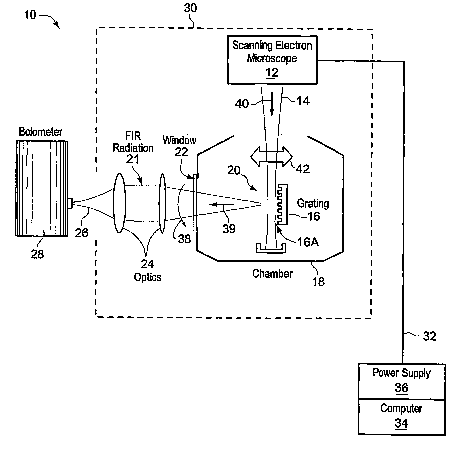
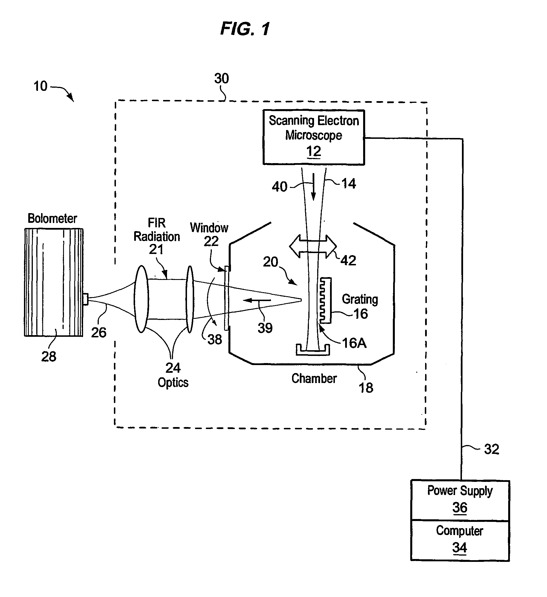
[0021]FIG. 1 depicts one embodiment of a free electron laser 10. A scanning electron microscope (SEM) 12 generates an electron beam 14, as shown. A grating 16 (illustratively mounted on a specimen stage within a specimen chamber 18) is positioned at the beam focus 20 of electron beam 14. FIR energy 21 scatters from grating 16 and exits chamber 18 through a window 22, for example made from polyethylene. Optics 24 (e.g., a pair of TPX (tetramethyl-1-pentene) lenses that exhibit optical refraction characteristics to FIR radiation 21) may be used to focus energy 21 into a laser beam 26. FIG. 1 also illustratively shows a detector 28 (e.g., a bolometer) that may be used to detect radiation of laser beam 26.

[0022] The size of grating 16 may affect the overall size of laser 10, which may for example be formed into a hand-held unit 30 attached by an umbilical 32 (e.g., containing electrical wiring and data busses) to a computer 34 and power source 36. For example, power supply 30 operating ...


PUM


Abstract

A system generates FIR laser radiation. An electron source generates an electron beam. A grating horn interacts with the electron beam to produce the FIR laser radiation. The grating horn may comprise a flat base and a pair of grating elements attached to the base, each of the grating elements being ruled with a grating period, the grating elements oriented in phase and in substantial symmetry about a normal to the flat base.

Description

RELATED APPLICATIONS [0001] This application claims priority to U.S. provisional application Ser. No. 60 / 414,119, filed Sep. 27, 2002, and hereby incorporated by reference.GOVERNMENT LICENSE RIGHTS [0002] The U.S. Government has certain rights in this invention as provided for by the terms of Grant #DAAD 19-99-1-0067 awarded by the Army Research Office, and of Grant #ECS-0070491 awarded by the National Science Foundation.BACKGROUND [0003] The terms “Terahertz” and “far infrared” (FIR) identify the range of the electromagnetic spectrum with free space wavelengths of about 10 to 1000 microns, or with wavenumbers from about 1000 to 10 cm−1. Humans have developed extensive technology to generate and detect electromagnetic waves or vibrations throughout the electromagnetic spectrum—from the very short wavelengths and very high frequencies of gamma rays to the very long wavelengths and very low frequencies of radio waves—with the exception of the far infrared (“FIR”) gap in the spectrum e...

Claims


Application Information

Patent Timeline
IPC IPC(8): H01S3/08G01J3/30H01S3/09
CPCH01S3/0903G02B5/1814
Inventor BROWNELL, JAMES HAYDEN
Owner QUALCOMM INC
Why Eureka
Try Eureka