Method and device for encoding and reconstructing computer-generated video holograms

a computer-generated, large-area technology, applied in the direction of holographic light sources/light beam properties, holographic processes, instruments, etc., can solve the problems of arbitrary depth, display surface, and 3d-autostereoscopic displays using conventional optics, and achieve the effect of substantially low refresh ra

Active Publication Date: 2006-03-09
SEEREAL TECHNOLOGIES
View PDF4 Cites 66 Cited by
  • Summary
  • Abstract
  • Description
  • Claims
  • Application Information

AI Technical Summary

Benefits of technology

[0025] It is an object of this invention to reconstruct video holograms in real-time using electronically controlled pixels arranged in an array with a minimal resolution (e.g. commercially available at reasonable cost for the mass market), a minimum of flickering and cross talk; reconstruction is simultaneous for both eyes over a large viewing area, so that the required refresh rate is substantially low.
[0028] It is further an object of the invention to provide a device for encoding and reconstructing video holograms using a flat and thin housing and that avoids costly and heavy optical and electronic hardware components with large physical dimensions.
[0036] If the horizontal positions of the observer's eyes change, the viewing windows are preferably tracked by displacing the column groups in relation to the image separation means. Alternatively, the image separation means, and in particular the separating elements, may be displaced in relation to the column groups. The use of horizontal line light sources facilitates viewing window tracking.
[0038] Tracking the viewing windows according to the positions of the observer's eyes in front of the display ensures that the holographic reconstruction is visible in a large zone at continuously high reconstruction quality.

Problems solved by technology

A drawback of 3D-autostereoscopic displays using conventional optics is a mismatch between parallax information and the accommodation of the lens of the eye.
This causes a mismatch between seeing objects at arbitrary depth (i.e. not on the display surface) achieved by parallax information and the accommodation of the eyes to the fixed display surface.
This may cause an unpleasant feeling and eye fatigue.
A major problem in encoding and reconstructing video holograms is that a sufficiently large viewing zone must be provided for viewing the reconstruction.
This causes costly hardware and long computation times even when the display is simplified to a horizontal-parallax only hologram.
Currently available large-area displays typically use holographic arrays with a pixel pitch which only diffracts light into a very small viewing zone, so that it is impossible to view a reconstructed three-dimensional scene with both eyes.
However, this arrangement has significant disadvantages: use of multiple displays and a large lens for reconstruction, leading to a large depth and large volume, and heavy demands on computing power.
Again, this method has the disadvantage of heavy demands on computing power.
In addition, the pixel arrays are required to have extremely short switching delays.
However, they suffer from substantial errors caused by binary encoding.
A common additional disadvantage of the cited known holographic methods is the heavy demand on computing power for encoding the holograms.
A consequence is much effort is done to project light into regions where no observer is located.
This area has to be limited such that light emanating from reconstructed scene points is confined to one viewing window.
Due to the low refresh frequency and long switching delays of available hardware, a sequential representation leads however to cross talk between the two eyes.

Method used


Image

  • Method and device for encoding and reconstructing computer-generated video holograms
  • Method and device for encoding and reconstructing computer-generated video holograms
  • Method and device for encoding and reconstructing computer-generated video holograms

Examples


Embodiment Construction

[0045] During the course of this description, like numbers will be used to identify like elements according to the different views that illustrate the invention.

[0046] In the preferred embodiment of the invention, the information about a three-dimensional scene is encoded in a transmissive holographic array, where the pixels are computer controlled according to the encoding to form a pixel pattern. However, the basic idea of the invention is not limited to the described transmissive holographic array. Both transflective and reflective holographic arrays or arrays that directly modulate the phase of the light waves, such as Freedericksz cells, may be used.

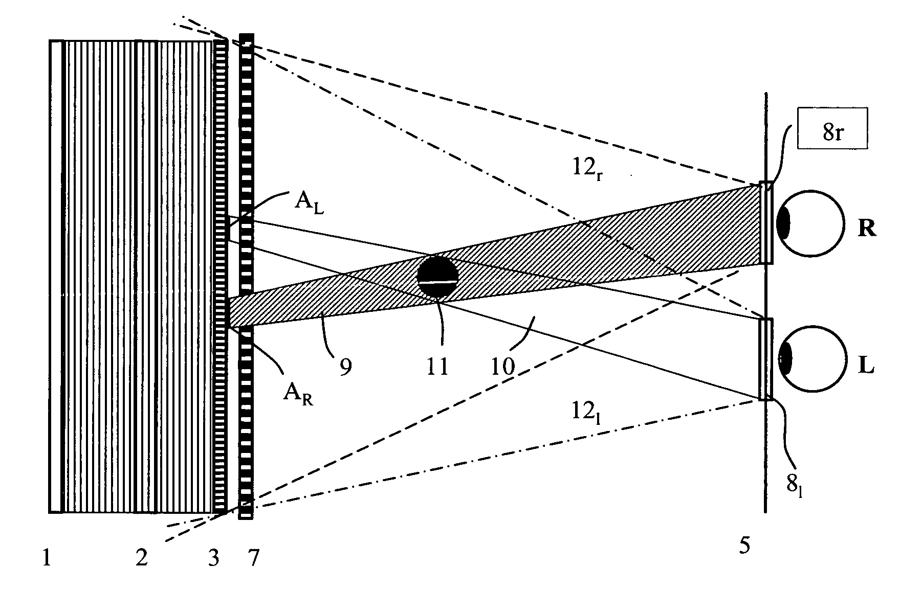
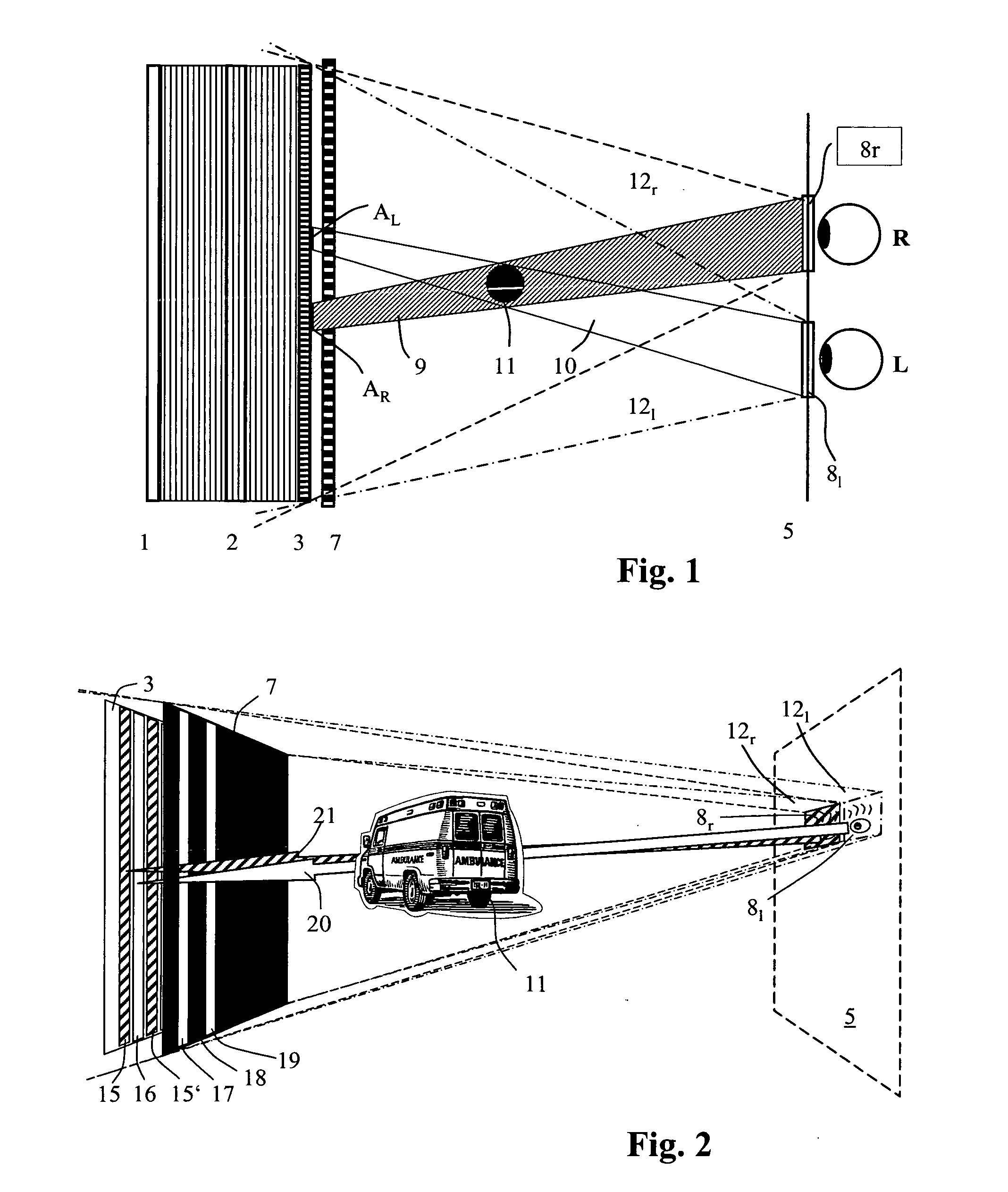
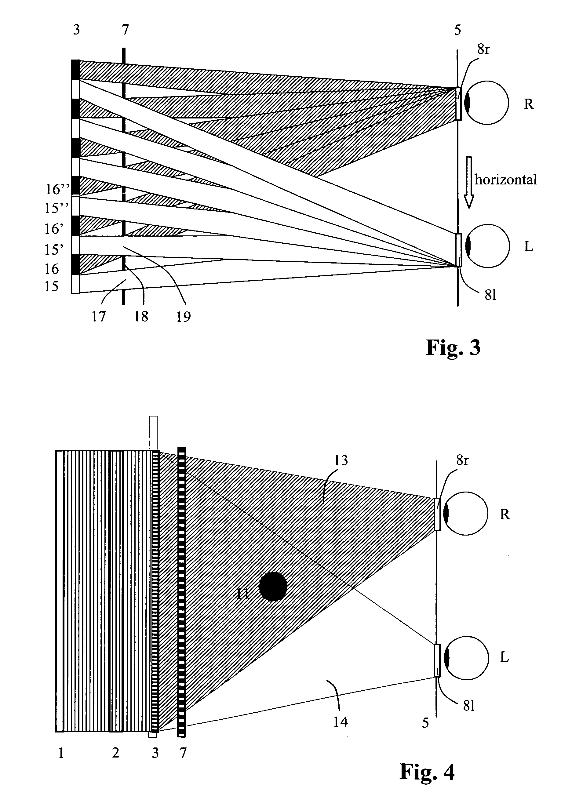
[0047]FIG. 1 shows a line light source 1 that illuminates, via focusing means 2, a holographic array 3. The focusing means 2 is a horizontally disposed cylindrical lens that images the light of the line light source 1 into a viewing plane 5 containing viewing windows 8r, 8l.

[0048]FIG. 1 relates to a holographic encoding of a sing...


PUM


Abstract

A method and a device for encoding and reconstructing computer-generated video holograms using a conventional LC display: it provides holographic reconstruction of three-dimensional scenes using electronically controllable pixel in a holographic array (3) with a conventional resolution, and is reasonably free from flickering and cross-talk. Reconstruction is in real time, and for both eyes at the same time, over a large viewing zone. The method takes advantage of an optical focusing means (2) in order to image vertically coherent light emitted by a line light source (1) into viewing windows (8R, 8L) after modulation by the pixel array (3). The holographic reconstruction (11) of the scene is rendered visible from viewing windows (8R, 8L) for both eyes of an observer by way of diffraction at the pixels. According to the invention, the controllable pixels are disposed in vertical pixel columns (15, 16), which encode separate holograms of the same scene for each of the viewer's eyes (R, L), where said holograms are one-dimensional in the vertical direction and horizontally interleaved. An image separation means (7) with separating elements arranged parallel to the pixel columns reveals the respective pixel columns (15, 15′ or 16, 16′) for one eye and covers them for the other eye.

Description

CROSS REFERENCE TO RELATED APPLICATIONS [0001] This application claims the priority of German application DE 10 2004 044 111.1 filed on Sep. 8, 2004, the entire contents of which is hereby incorporated in total by reference. BACKGROUND OF THE INVENTION [0002] 1. Field of the Invention [0003] The invention relates to a method and device for encoding and reconstructing computer-generated large-area video holograms using a display with conventional (i.e. commercially available) resolution; the display gives a large viewing angle and a high spatial image quality. The display includes a holographic array with controllable pixels, which electronically affect the amplitude and / or phase of light. Such an array is known as spatial light modulator (SLM). A suitable array for spatial amplitude modulation of a light pattern to reconstruct video holograms is, for example a Liquid Crystal Display (LCD). However, this invention can also be applied to other controllable holographic arrays, which us...

Claims


Application Information

Patent Timeline
Patent Type & Authority Applications(United States)
IPC IPC(8): G02B27/22G02B5/32
CPCG03H1/22G03H2210/30G03H1/2286G03H1/2294G03H2001/0421G03H2001/2236G03H2001/2242G03H2001/303G03H2222/22G03H2223/12G03H2226/05G03H2227/02G03H2227/05H04N13/0409H04N13/0411G03H1/2249G03H1/2205H04N13/312H04N13/31
Inventor SCHWERDTNER, ARMINHAUSSLER, RALFLEISTER, NORBERT
Owner SEEREAL TECHNOLOGIES
Why Eureka
Try Eureka