Standard wave receiver and time code decoding method

Inactive Publication Date: 2006-03-09
LAPIS SEMICON CO LTD
View PDF6 Cites 40 Cited by
  • Summary
  • Abstract
  • Description
  • Claims
  • Application Information

AI Technical Summary

Benefits of technology

[0009] It is an object of the invention to provide a standard wave receiver and a time code decoding method that

Problems solved by technology

Therefore, under a reception environment with extremely inferior noise intensity, field intensity, or the like,

Method used


Image

  • Standard wave receiver and time code decoding method
  • Standard wave receiver and time code decoding method
  • Standard wave receiver and time code decoding method

Examples


first embodiment

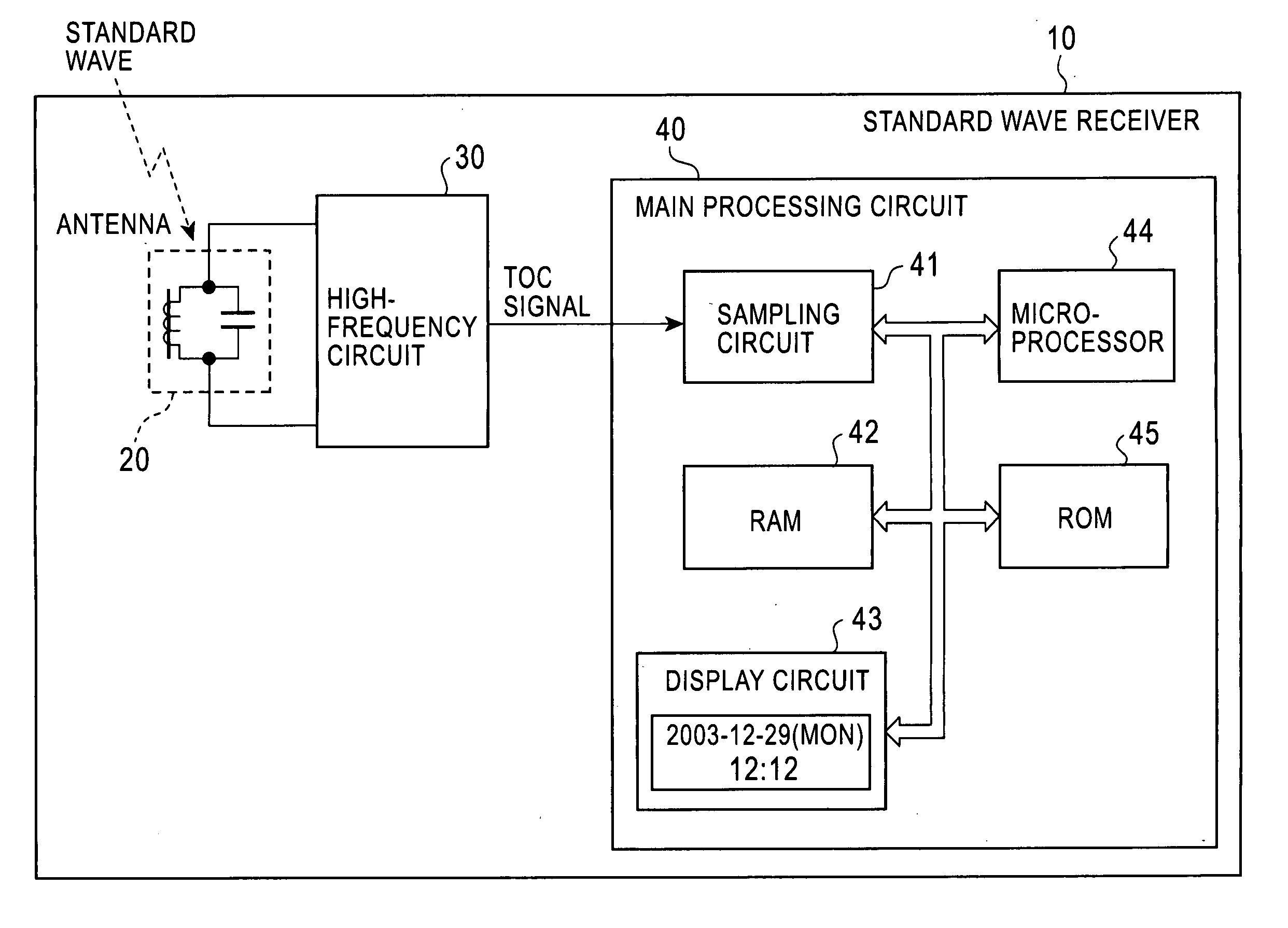
[0032]FIG. 3 shows a structure of a standard wave receiver in the invention. The standard wave receiver executes a time code decoding method according to the invention. Referring to the figure, a standard wave receiver 10 includes an antenna 20, a high-frequency circuit 30, and a main processing circuit 40. The main processing circuit 40 includes a sampling circuit 41, a RAM 42, a display circuit 43, a microprocessor 44, and a ROM 45. The standard wave receiver 10 could be, for example, a device such as a radio controlled watch (clock) that calibrates displayed time on the basis of time data of a standard wave.

[0033] The antenna 20 is a receiving antenna for long waves, such as a bar antenna. The antenna 20 receives a standard wave and supplies the standard wave to the high-frequency circuit 30. The high-frequency circuit 30 amplifies and detects such a received wave, extracts a time code signal (hereinafter referred to as TCO signal) carried on the standard wave, and supplies the T...

third embodiment

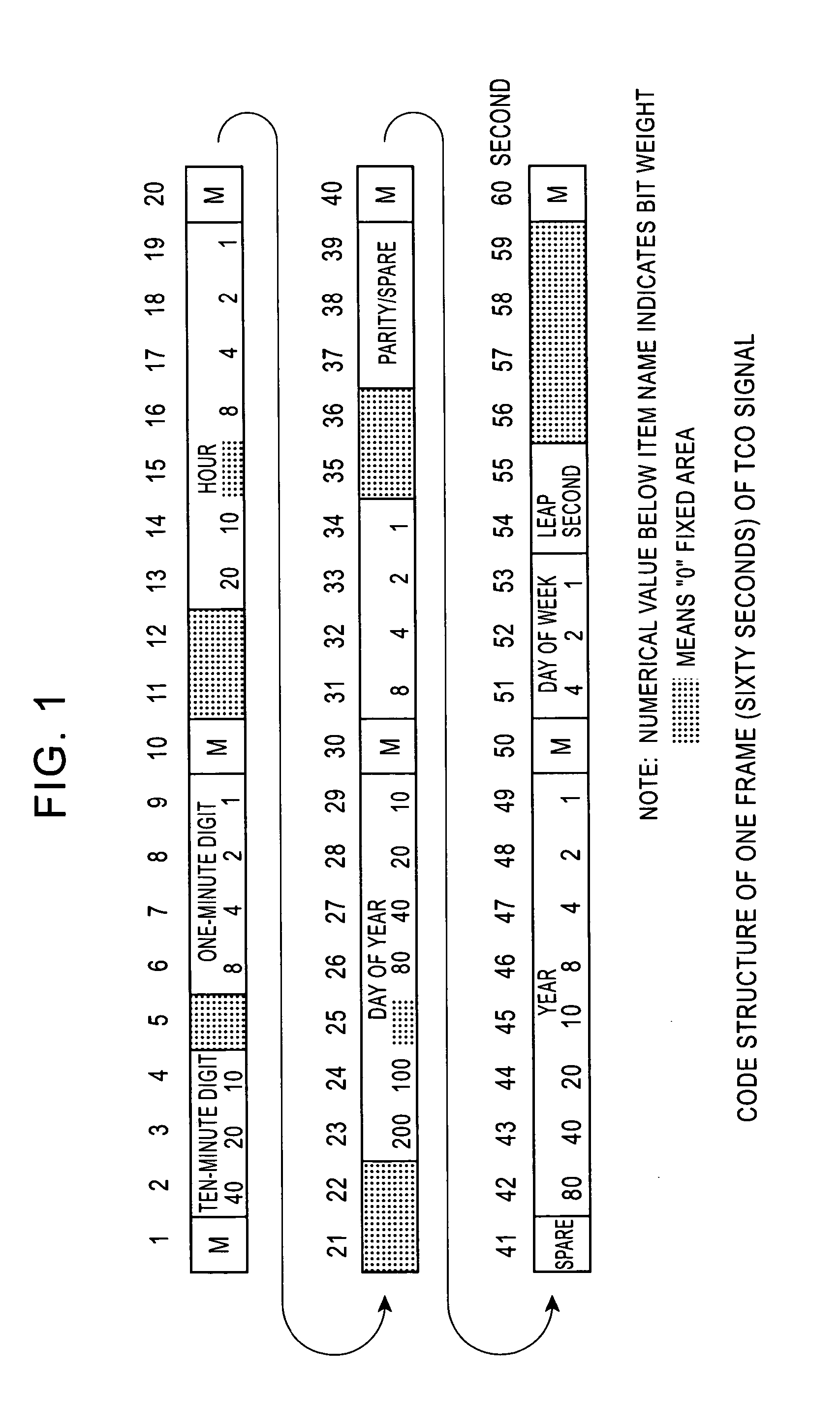
[0039] Next, the standard wave receiver 10 performs position marker position detection and an on-the-minute marker position detection with respect to the code sequence (step S105). The position marker position detection and the on-the-minute marker position detection are executed using systems for statistic marker position detection and statistic on-the-minute marker position detection. Such systems will be explained in detail in a Subsequently, the standard wave receiver 10 checks the accumulated sampling data with a format of time codes to recognize digit positions of the respective time codes including a one-minute digit code, a ten-minute digit code, an hour digit code, a day of year digit code, a year digit code, and a day of week digit code (step S106).

[0040] Next, concerning a one-minute digit with a largest change, the standard wave receiver 10 uses an analytical decoding system, which is devised focusing on the periodicity of the one-minute digit, to acquire time data of t...


PUM


Abstract

A standard wave receiver and a time code decoding method, which receive a standard wave including a time code signal, in which one frame including plural time codes is repeated, and decode the time codes, are provided. The time code signal is sampled over a period, in which a plurality of the frames continue, and sampled value sequences including plural sampled values generated in time series are accumulated. The sampled value sequences are convolutionally added every predicted period of a marker code indicating a leading position of the frame to generate an added value sequence and a position of the marker code is determined on the basis of the added value sequence. Positions of the respective plural time codes are determined in accordance with the determined position of the marker code and, for each of the time codes, partial sampled value sequences, which corresponds to a position of the time code and is expected to take an identical value, is extracted out of the sampled value sequences, the partial sampled value sequences are convolutionally added to generate an added value sequence, and a value of the time code is determined on the basis of the added value. This makes it possible to decode a time code signal precisely even under an inferior reception environment.

Description

BACKGROUND OF THE INVENTION [0001] 1. Field of the Invention [0002] The present invention relates to a standard wave receiver that receives a standard wave and presents clock time, and a time code decoding method of decoding a time code signal superimposed on the standard wave. [0003] A standard wave providing the Japanese Standard Time is always transmitted by long waves of 40 kHz and 60 kHz from two locations in Japan, the Kyushu Long Wave Station and the Fukushima Long Wave Station that are operated and managed by the Communication Research Laboratory. A carrier wave of such a standard wave is subjected to amplitude modulation according to a time code signal (hereinafter also referred to as TCO signal) that is generated at a bit rate of 1 bit / second. In the time code signal, one frame consisting of 60 bits is repeated every one minute. Time information including year, month, day, hour and minute is stored in each frame in a notation form of a Binary Coded Decimal code (BCD) (see ...

Claims


Application Information

Patent Timeline
IPC IPC(8): H04L7/00G06F1/06G04G5/00G04R20/00G04R20/12
CPCG04G5/002G04R20/12G04G21/04
Inventor KONDO, TAKAYUKI
Owner LAPIS SEMICON CO LTD
Why Eureka
Try Eureka