
Fluid dynamic pressure bearing

a dynamic pressure bearing and bearing technology, applied in the direction of bearings, shafts and bearings, rotary bearings, etc., can solve the problems of insufficient supply of lubricating oil and difficulty in moving lubricating oil, and achieve the effects of easy plastic work, high working accuracy and high strength

Inactive Publication Date: 2006-03-09
HITACHI POWDERED METALS COMPANY
View PDF3 Cites 15 Cited by
  • Summary
  • Abstract
  • Description
  • Claims
  • Application Information

AI Technical Summary

Benefits of technology

[0010] Therefore, an object of the present invention is to provide a high performance fluid dynamic pressure bearing which can have good bearing rigidity even under high temperature conditions as a bearing for motors such as spindle motors of compact, thin, and high speed types.
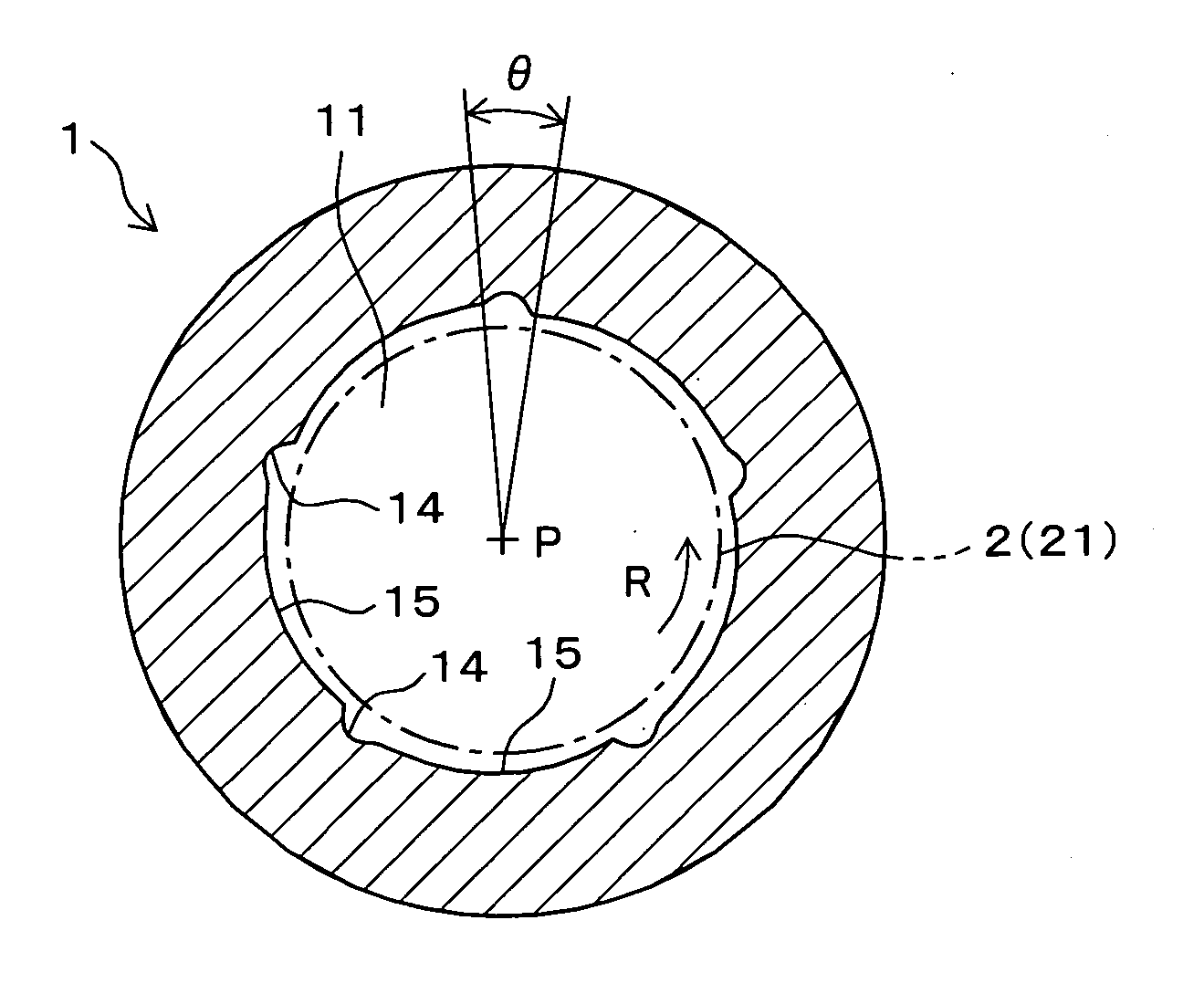
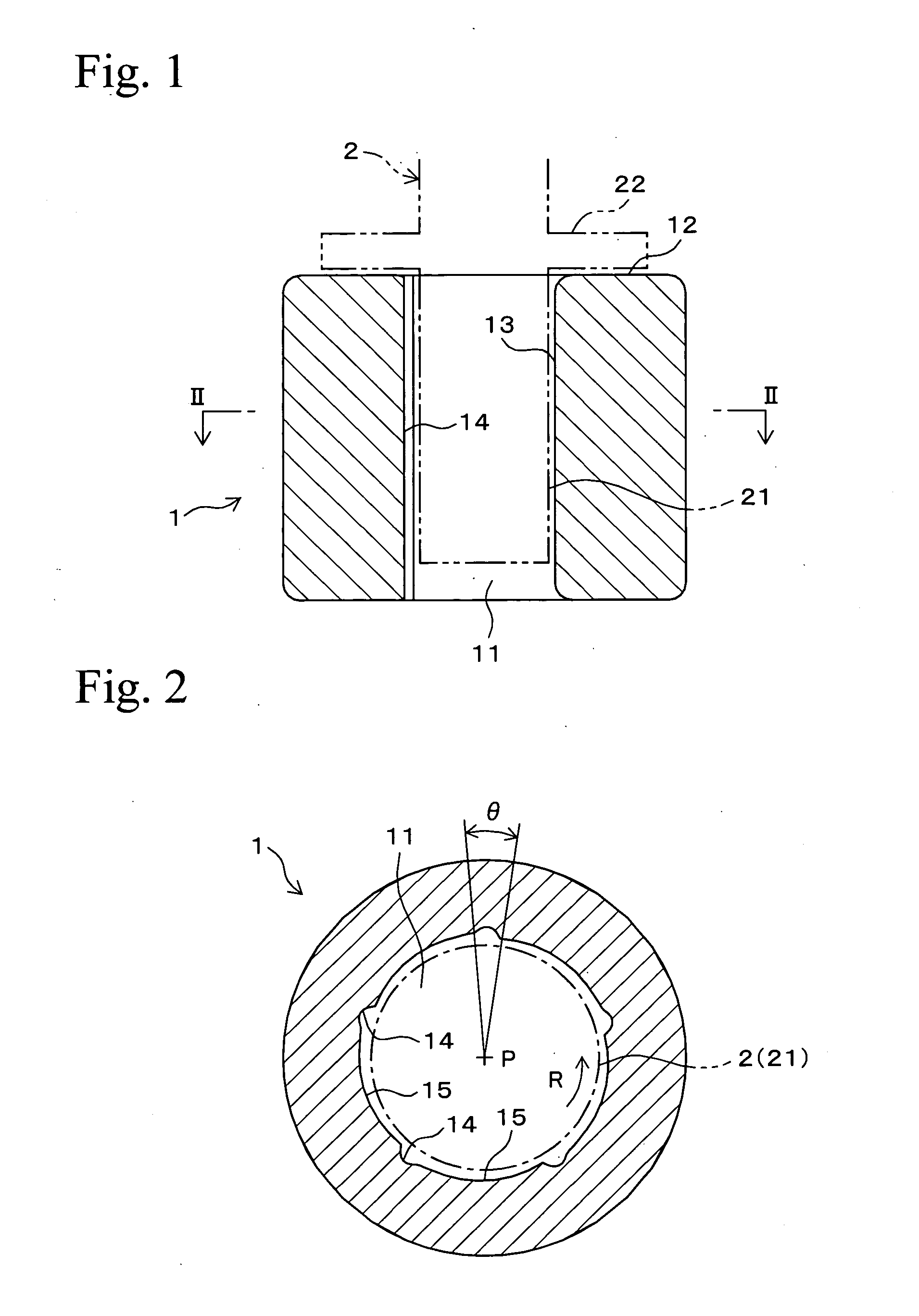
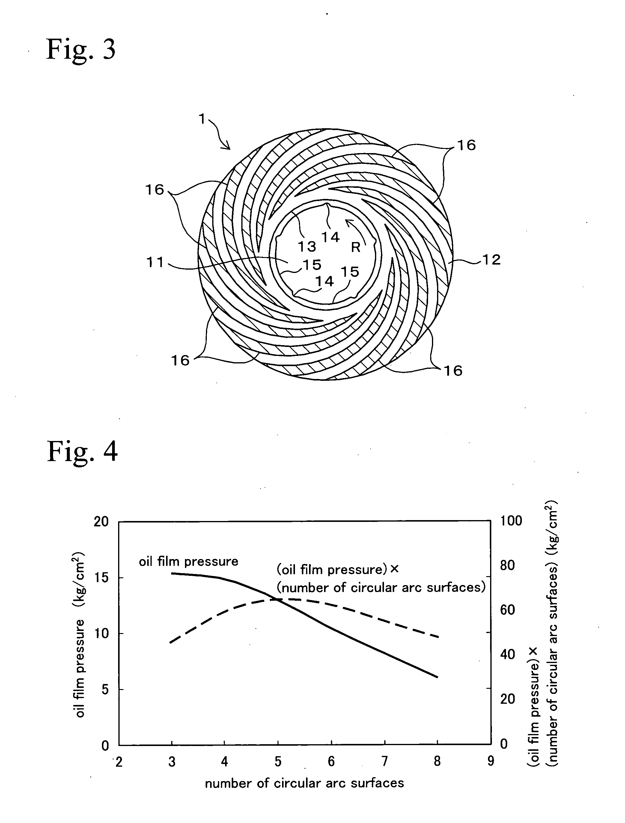
[0011] The Inventors intensively researched on the shapes, the numbers, and the sizes, etc., of the above radial recessed portions and thrust recessed portions for generating dynamic pressure. The Inventors obtained the following findings. That is, the radial recessed portions for generating dynamic pressure are desirably circular arc surfaces, and in the case in which the number of the circular arc surfaces is 3 to 6, the radial recessed portions are easily formed and high bearing rigidity can be obtained. Separation grooves for supplying a lubricating oil between the circular arc surfaces extend in an axial direction, and divide an inner peripheral surface in a circumference direction to separate the circular arc surfaces from each other. The separation grooves are desirably formed so as to divide an inner peripheral surface into 3 to 6 portions in a circumferential direction. The separation groove desirably has a width corresponding to an angle of 8 to 20 degrees in the circumferential direction of which a center is an axial center of the bearing, and has a maximum depth of 0.05 to 0.15 mm.
[0016] A sintered member formed by compacting a material powder into a green compact and sintering the green compact is desirably used for a material of the fluid dynamic pressure bearing of the present invention since the sintered member can be easily plastic worked. The sintered bearing is desirably made of a sintered alloy including 40 to 60 mass % of Fe, 40 to 60 mass % of Cu, and 1 to 5 mass % of Sn, since high working accuracy and high strength can be obtained.
[0017] According to the fluid dynamic pressure bearing of the present invention, since the shapes, the numbers, and the sizes, etc., of the radial recessed portions and the thrust recessed portions for generating dynamic pressure are set to the optimum conditions, superior bearing rigidity can be obtained under high temperature conditions, and the fluid dynamic pressure bearing is the most promising as a bearing for motors such as spindle motors of compact, thin, and high speed types.

Problems solved by technology

In the case in which the angle corresponding to the width of the separation groove is less than 8 degrees, the dynamic pressure is higher, but it is difficult to move the lubricating oil by the rotation of the shaft, and the supply of the lubricating oil is insufficient.

Method used


Image

  • Fluid dynamic pressure bearing
  • Fluid dynamic pressure bearing
  • Fluid dynamic pressure bearing

Examples


examples

[0039] Next, examples of the present invention will be explained, and the effects of the present invention will be confirmed.

[0040] A raw powder having composition shown in Table 1 was compacted into a green compact, and the green compact was sintered, so that the required number of materials of a cylindrical sintered bearing was obtained. The material of a sintered bearing had a true density ratio of 6.3 to 7.2%, an outer diameter of 6 mm, and an axial direction length of 5 mm. Next, the materials of a sintered bearing were worked, and tests regarding the following points A to E were performed thereon.

TABLE 1(mass %)CuSnFe40 to 601 to 540 to 60

[0041] Test A. Number of Separation Grooves and Circular Arc Surfaces

[0042] Six kinds of sintered bearings having 3 to 8 separation grooves and 3 to 8 circular arc surfaces of inner peripheral surfaces were made. The separation grooves and the circular arc surfaces were formed by plastic working such that a male pin for forming separation...


PUM


Abstract

A cylindrical fluid dynamic pressure bearing includes: a shaft hole which has an inner peripheral surface and into which a shaft is inserted; plural separation grooves formed at equal intervals on the inner peripheral surface in a circumferential direction, the separation grooves extending in an axial direction and dividing the inner peripheral surface in the circumferential direction; and circular arc surfaces formed on the inner peripheral surface between the separation grooves, the circular arc surfaces being eccentric with respect to a center of an outer diameter of the bearing and being inwardly biased toward one circumferential direction, wherein the number of the separation grooves is 3 to 6, the number of the circular arc surfaces is the same as the number of the separation grooves, and the separation groove has a width corresponding to an angle of 8 to 20 degrees in the circumferential direction of which a center is an axial center of the bearing, and has a maximum depth of 0.05 to 0.15 mm.

Description

BACKGROUND OF THE INVENTION [0001] 1. Field of the Invention [0002] The present invention relates to a fluid dynamic pressure bearing which can provide high levels of bearing rigidity by generating a dynamic pressure in a lubricating fluid such as a lubricating oil, and in particular relates to a fluid dynamic pressure bearing desirably used for, for example, spindle motors of compact, thin, and high speed rotation types. [0003] 2. Description of Related Art [0004] For example, in various kinds of information devices such as disc drive devices which read and write information from and to a magnetic disc or an optical disc such a CD or a DVD, spindle motors are used as driving devices. In addition, in mirror drive devices such as laser printers, spindle motors are used as driving devices. In the spindle motors, ball bearings are used as bearings, but have limitations of rotation accuracy, high speed, and low noise. Therefore, non-contact types of fluid dynamic pressure bearings super...

Claims


Application Information

Patent Timeline
IPC IPC(8): F16C32/06
CPCF16C33/1065F16C17/045F16C17/028
Inventor NII, KATSUTOSHISHIKATA, HIDEO
Owner HITACHI POWDERED METALS COMPANY
Learn More