Axial compliance mechanism of scroll compressor

a technology of axial compliance and scroll compressor, which is applied in the direction of liquid fuel engines, machines/engines, rotary piston liquid engines, etc., can solve the problems of lateral force and deformation, unwanted frictional damage, leakage from the end panels or the side surfaces of the wraps, etc., and achieve the effect of improving the volume efficiency of the compressor

Inactive Publication Date: 2006-03-09
FUSHENG IND CO LTD
View PDF7 Cites 21 Cited by
  • Summary
  • Abstract
  • Description
  • Claims
  • Application Information

AI Technical Summary

Benefits of technology

[0006] The present invention provides an axial compliance mechanism of a scroll compressor. A negative pressure chamber is formed between a first shell and a fixed scroll. In compression operation, the working fluid is guided into the negative pressure chamber to force the fixed scroll closely attach to the orbiting scroll, so as to enhance the volume efficiency of the compressor.

Problems solved by technology

The axial, radial and tangential forces cause leakage from the end panels or the side surfaces of the wraps.
However, as the orbiting scroll member has to overcome the axial force and the biasing torques, an excessive pressure is typically resulted to cause unwanted frictional damage.
However, as the spacer is fixed in the top shell, and the fixed and orbiting scrolls are fixed in the bottom shell, lateral force and deformation are inevitable during the welding process.
As the concentric requirement between the hole of the spacer, the tubular neck of the fixed scroll and the rotation part of the motor is rather high, the yield is typically low.
When many devices are required by the compressor, this greatly increases material and fabrication cost.
In addition, when the working fluid is discharged from the venting port of the top shell, the pressure applied to the pressurizing members is uneven to cause unbalance by the fixed scroll, such that high noise and friction between devices are generated.

Method used


Image

  • Axial compliance mechanism of scroll compressor
  • Axial compliance mechanism of scroll compressor
  • Axial compliance mechanism of scroll compressor

Examples


Embodiment Construction

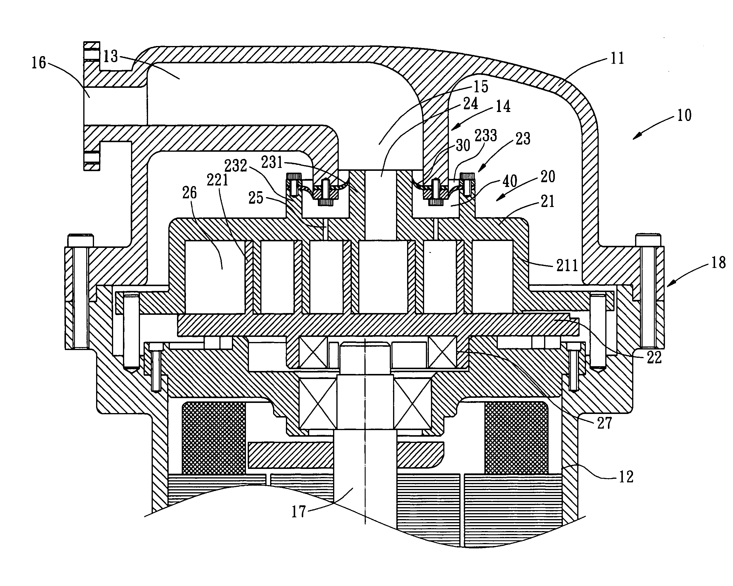
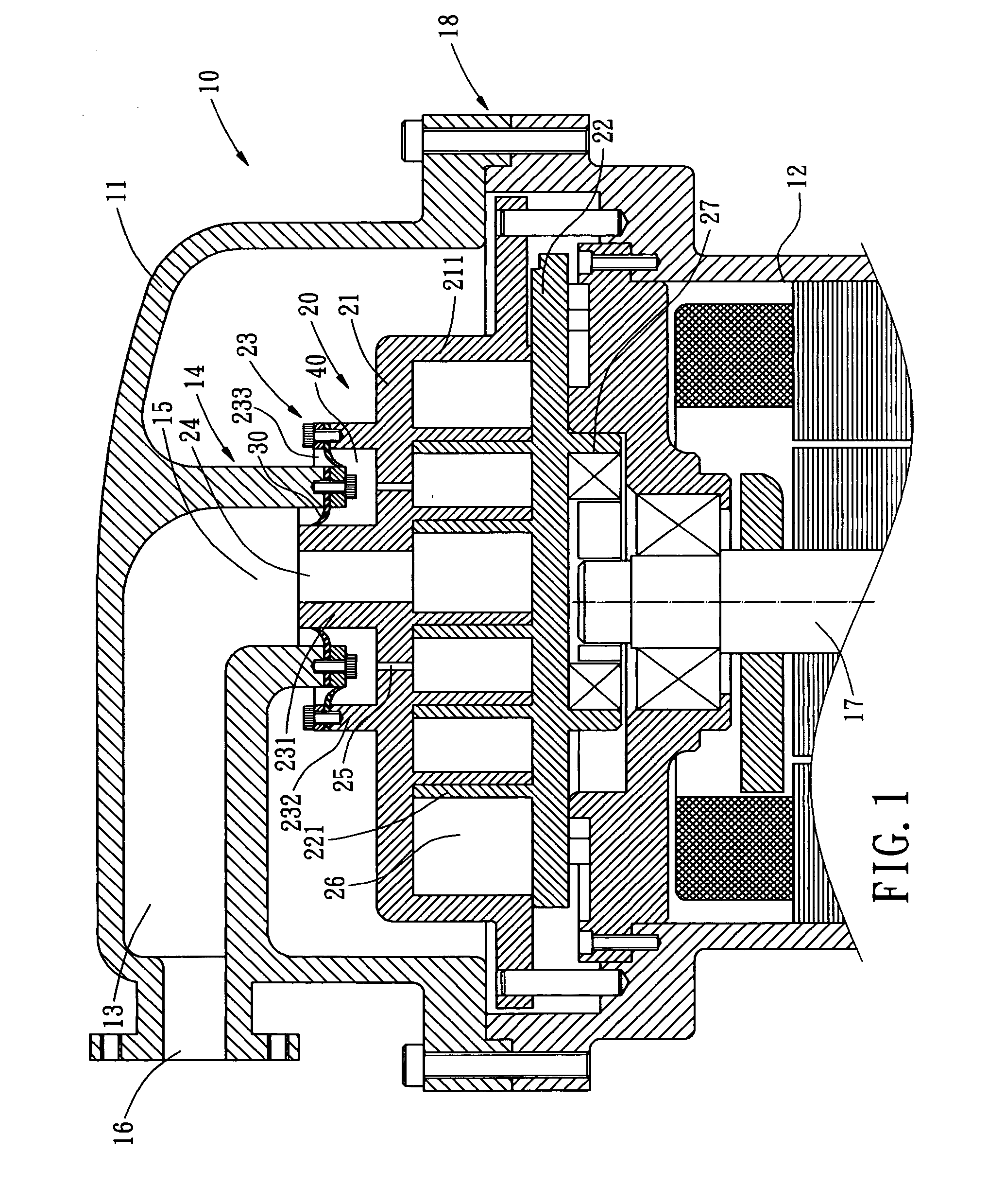
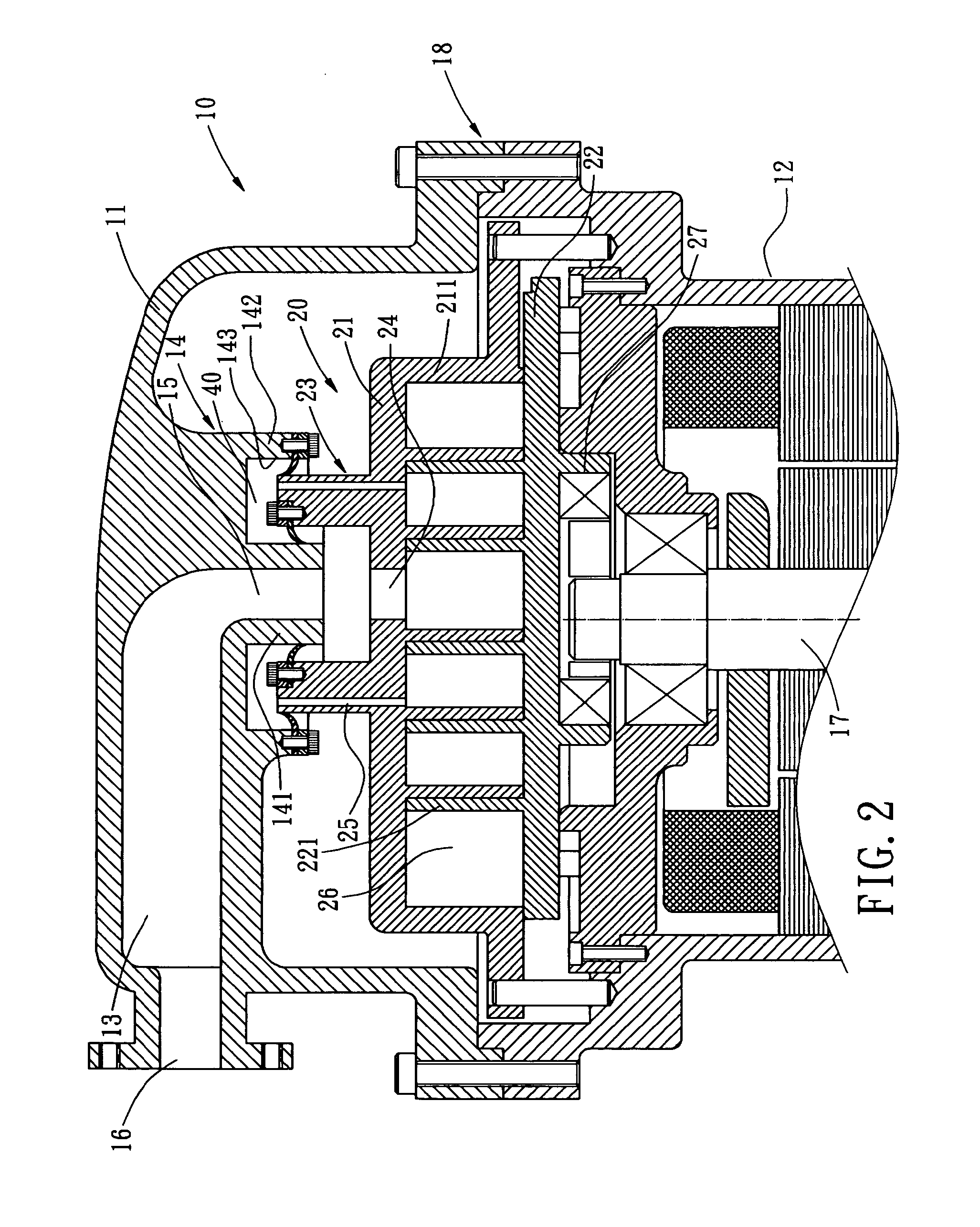
[0017] Referring to FIG. 1, a cross sectional view of a first embodiment of an axial compliance mechanism for a scroll compressor is shown. As shown, the scroll compressor comprises a housing 10 and a scroll device 20, and the axial compliance mechanism is installed between the housing 10 and the scroll device 20.

[0018] The housing 10 has a first shell 11 and a second shell 12. Each of the shells 11 and 12 has a hollow chamber. Fastening members such as screws or welding or soldering process can be used to attach the first shell 11 on top of the second shell 12. The first shell 11 has a closed chamber 13. Extending from one end of the closed chamber 13 includes a guiding part 14. The guiding part 14 is preferably in the form of a cylinder. The bottom of the closed chamber 13 has a hole 15, while the other end of the closed chamber 13 has a venting hole 16. The second shell 12 has an inlet port (not shown) allowing the working fluid to flow therein. Various compressor devices, actua...


PUM


Abstract

An axial compliance mechanism of a scroll compressor is installed between a compressor housing and a scroll. The housing has a first shell and a second shell. The first shell defines a chamber and has a guiding part at one end of and in communication with the interior of the chamber. The scroll has a fixed scroll member and an orbiting scroll member. A plurality of compression pockets is formed between these two scroll members. A rear surface of the fixed scroll member has a protrusion matching the guiding part of the first shell and a venting hole in communication with the compression chambers. A sealing device is installed between the guiding part and the protrusion, and a negative pressure chamber is formed. Thereby, the working fluid is guided into the negative pressure chamber during operation, so as to provide a tight attachment between the fixed scroll member and the orbiting scroll member, such that the volume efficiency of the compressor is enhanced.

Description

BACKGROUND OF THE INVENTION [0001] The present invention relates in general to an axial compliance mechanism of a scroll compressor, and more particularly, to a structure for improving axial sealing compliance of a scroll. [0002] A typical scroll compressor includes two scroll members, namely, a fixed scroll and an orbiting scroll. The orbiting scroll revolves about the fixed scroll. In compression operation, the fixed scroll and the orbiting scroll each has an involute wrap inter-fitting each other to allow working fluid entering a compression chamber through a suction port thereof. The continuous revolutions of the orbiting scroll further provide compression of the working fluid until the working fluid is discharged from an inner discharge port of the fixed scroll to complete the compression process of the working fluid. During the compression operation, the volume of the working fluid is reduced, while the pressure thereof is increased. Thereby, axial force, radial force and tang...

Claims


Application Information

Patent Timeline
Patent Type & Authority Applications(United States)
IPC IPC(8): F04C18/00F04C2/00F03C4/00
CPCF04C27/005F04C18/0215
Inventor TARNG, GUANG-DER
Owner FUSHENG IND CO LTD
Why Eureka
Try Eureka