
Structure of interfolding machine

a technology of interfolding machine and structure, which is applied in the direction of paper/cardboard containers, envelope/bag making machinery, box making operations, etc., can solve the problem of inflexible production process, and achieve the effect of high flexibility

Active Publication Date: 2006-03-09
MTC MACCINE TRASFORMAZIONE CARTA SRL
View PDF12 Cites 13 Cited by
  • Summary
  • Abstract
  • Description
  • Claims
  • Application Information

AI Technical Summary

Benefits of technology

[0014] It is therefore a feature of the present invention to provide a structure of an interfolding machine that provides stacks of interfolded sheets of different length easily and cheaply causing the whole production process to be flexible, allowing different products to exit from a same machine.
[0023] In this way, with a single interfolding machine having more removable portions each with rollers of different diameter it is possible to provide stacks of interfolded sheets of different length so that the machine is highly flexible.

Problems solved by technology

For this reason each interfolding machine causes the production of interfolded sheets of a single length, whereby the production process is not flexible.

Method used


Image

  • Structure of interfolding machine
  • Structure of interfolding machine
  • Structure of interfolding machine

Examples


Embodiment Construction

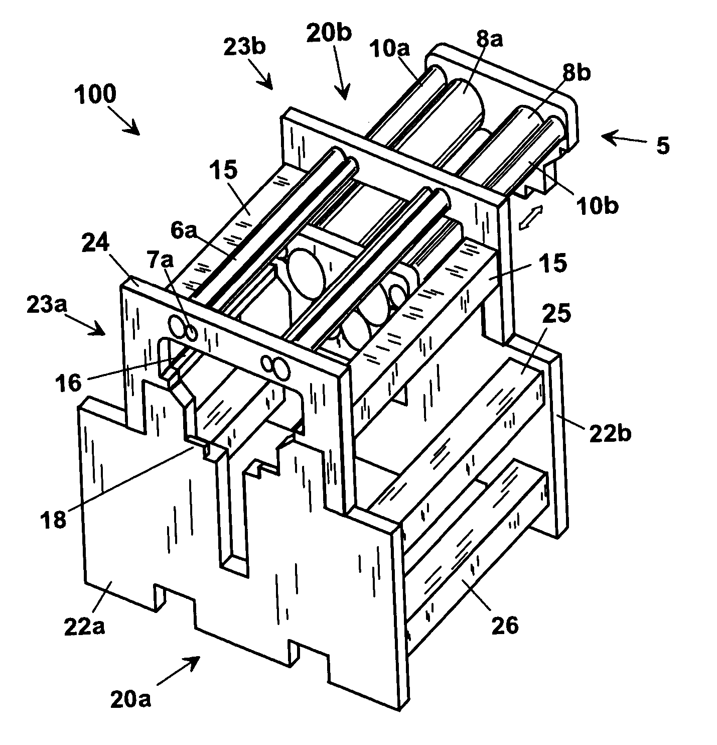
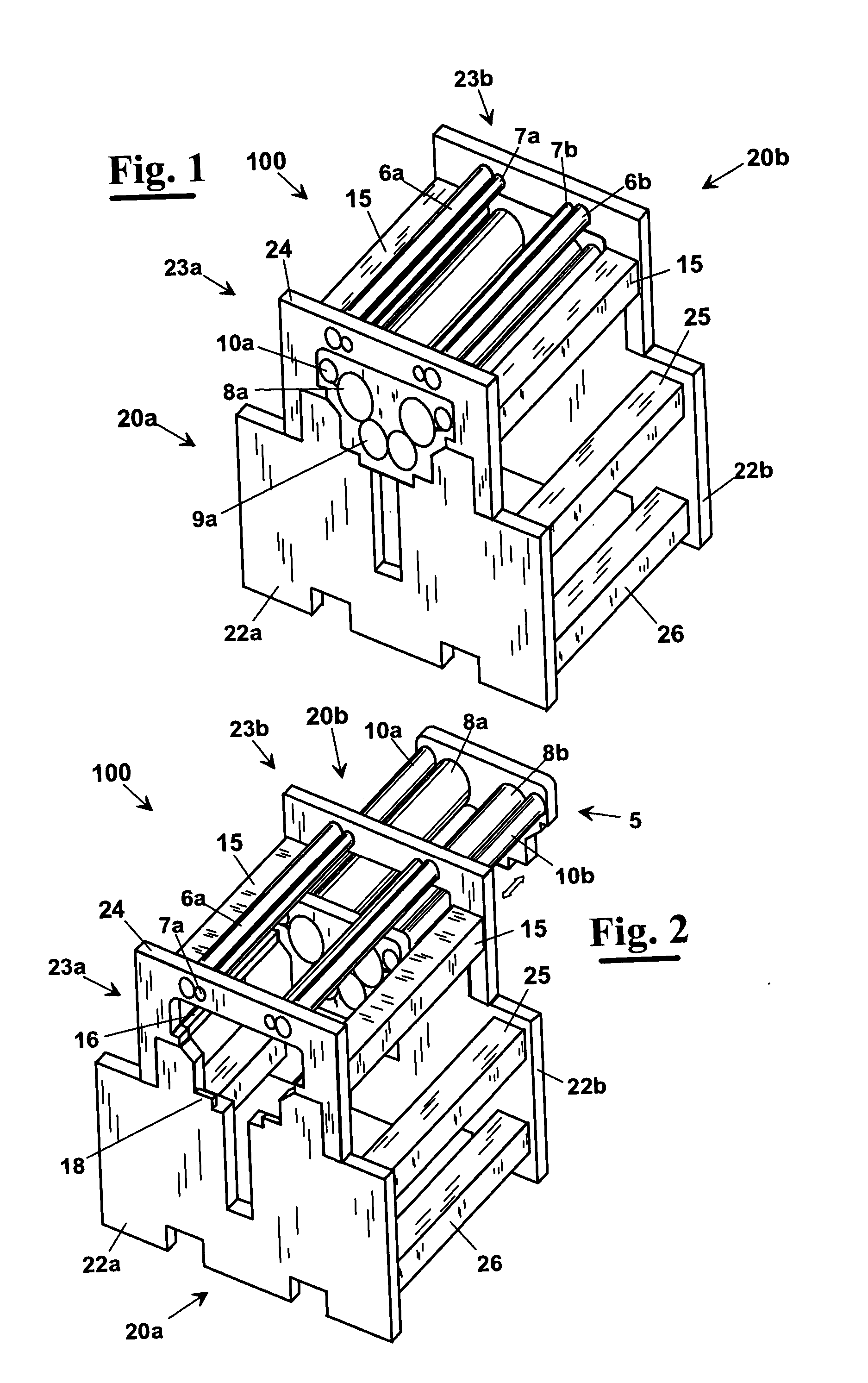
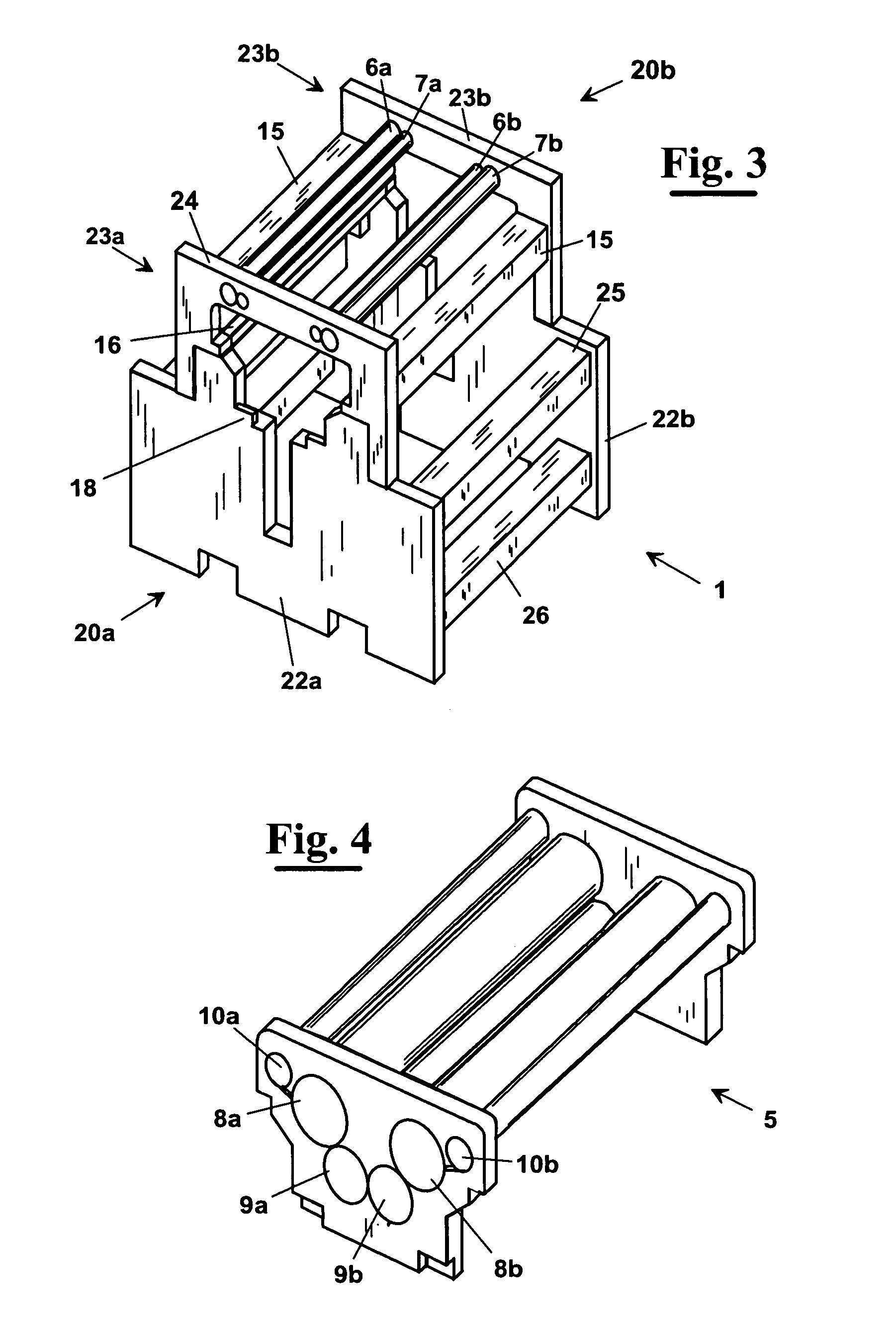
[0037] With reference to FIG. 1, an interfolding machine, according to the present invention, has a modular structure. In particular, the interfolding machine 100 provides a framework 1 (visible alone in FIG. 3) comprising a first plate 20a and a second plate 20b, parallel to it, interconnected by means of beams 15, 25 and 26. More in detail, each plate 20a, or 20b, has a modular structure and comprises at least one lower portion 22a, or 22b, and an upper portion 23a, or 23b. The upper portions 23a and 23b of the plates 20a and 20b in FIGS. from 1 to 3 are connected by beams 25, whereas the lower portions 22a and 22b are connected by beams 26 and 15.

[0038] In particular, the upper portion has a portion 5 removable independently from the framework 1. More in detail, the removable portion 5, as in the case shown in FIGS. from 1 to 5, comprises the cutting rollers 8, the relative rollers that bring the cutting tool 10 and the folding rollers 9. Whereas the web conveying rollers 6 and ...


PUM

PropertyMeasurementUnit
Diameteraaaaaaaaaa
Lengthaaaaaaaaaa
Sizeaaaaaaaaaa

Abstract

An interfolding machine having a framework (1) comprising a first plate (20a) and a second plate (20b), parallel to each other, interconnected by means of beams (15, 25, 26). Each plate (20a or 20b), has a modular structure and comprises at least one lower portion (22a or 22b) and an upper portion (23a or 23b). The upper portions (23a, 23b) of the plates (20a, 20b) are connected by beams (25), whereas the lower portions (22a, 22b) are connected by relative beams (26, 15). The upper portion has a portion (5) removable independently from the framework (1). The removable portion (5) comprises cutting rollers (8), the rollers bringing a cutting tool (10) and folding rollers (9). The web conveying rollers (6, 7), conveying the paper along the direction of process are mounted on the fixed portion (24) of the upper portion (23) of the framework (1).

Description

CROSS REFERENCE TO RELATED APPLICATIONS [0001] This application claims priority of European Patent Application No. 04425654.3, filed Aug. 31, 2004, which application is incorporated herein by reference. FIELD OF THE INVENTION [0002] The present invention relates to the production of paper material in stacks of interfolded sheets and in particular it relates to a structure of an interfolding machine capable of processing sheets of different length. BACKGROUND OF THE INVENTION [0003] As is well known, in the industry of paper a variety of types of machines and of processes exist for making paper tissues, paper towels and the like by producing stacks of interfolded sheets of a certain height. [0004] They are obtained by folding the sheets in an “interfolded” way, namely folding into panels by overlapping at the same time a panel of a previous sheet with a panel of a following sheet. In this way, when pulling a sheet from the stack, at the moment of the use also a panel of the following...

Claims


Application Information

Patent Timeline
IPC IPC(8): B31B49/00B31B50/00B65H45/24B65H45/28
CPCB65H45/24B65H2402/40B65H2402/10
Inventor DE MATTEIS, ALESSANDRO
Owner MTC MACCINE TRASFORMAZIONE CARTA SRL
Learn More