Unlock instant, AI-driven research and patent intelligence for your innovation.

Modular dehumidifier

a dehumidifier and module technology, applied in the field of compact dehumidifiers, can solve the problems of reducing the capacity of the dehumidifier, occupying a lot of space, and cumbersome movemen

Inactive Publication Date: 2006-03-16
WHIRLPOOL CORP
View PDF7 Cites 34 Cited by
  • Summary
  • Abstract
  • Description
  • Claims
  • Application Information

AI Technical Summary

Benefits of technology

[0013] A dehumidifier comprises a housing having an inlet and an outlet and defining an air flow path from the inlet to the outlet, a blower located within the air flow path and operable to draw air into the inlet and expel air through the outlet, a heat exchanger located within the air flow path, and a compressor fluidly connected to the heat exchanger and at least a portion of the compressor is located within the air flow path such that air flowing through the air flow path cools the compressor.

Problems solved by technology

This configuration results in a relatively tall and / or wide configuration, which takes up a lot of space in the room and which is cumbersome to move.
Unfortunately, the design of current dehumidifiers requires a reduction in dehumidifier capacity, either moisture removal rate or the size of the collection bucket, to obtain a smaller configuration.
However, either of these capacity reductions have negative consequences for at least some segment of the consumers.
The reduction in the rate of moisture removal means the dehumidifier may not be able to meet the consumer's needs in drying out a room, especially if it is a larger room or has higher humidity.
This puts a great burden on the manufacturer to create a design that meets or closely meets both the consumer's functional and cost needs.
From the manufacturer's viewpoint, while the air treatment appliances do often share common components, the components in one appliance for one function may not be optimized for another function, leading to the appliance.
Often the manufacturer will design for the worst case function, which can lead to over design for the other functions.
This has the tendency to increase the cost to the consumer, which is undesirable.
Therefore, there is a strong desire and need for manufacturers to provide consumers with as few air treatment appliances as possible to meet the consumer's air treatment needs while minimizing the cost, which is a very difficult task.

Method used


Image

  • Modular dehumidifier
  • Modular dehumidifier
  • Modular dehumidifier

Examples


Embodiment Construction

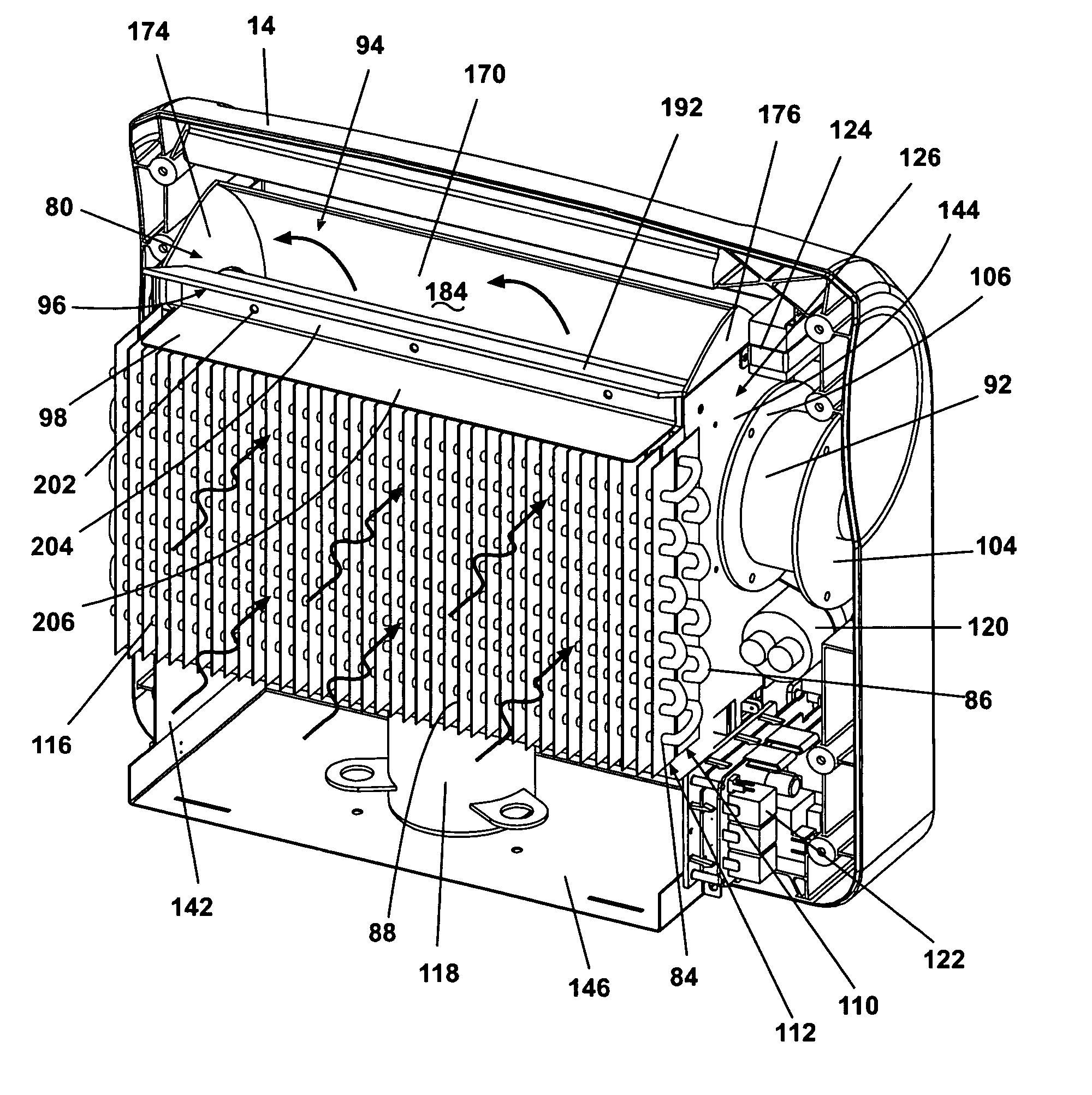
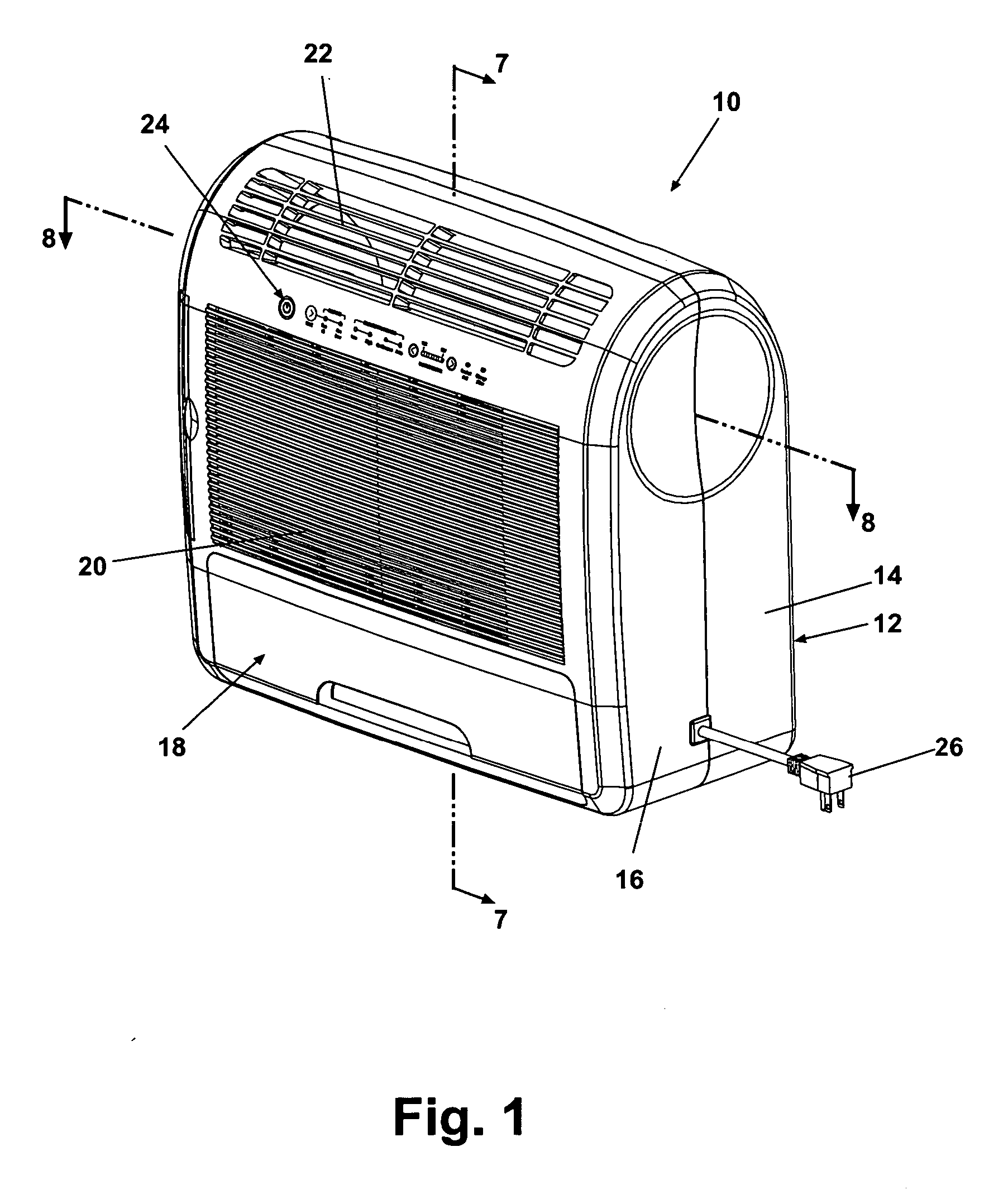
[0051] Referring to the Figures, and in particular to FIG. 1, a modular portable air treatment device 10 is shown comprising a housing assembly 12 having a rear housing 14 and a front housing 16 in abutting cooperative registry. The housing assembly 12 encloses various operable components which will be described hereinafter. The front housing 16 has a front grille 20 extending generally over the front face of the housing 16, and a top grille 22 above the front grille 20 oriented for directing an upward flow of air therethrough. Thus, with respect to the direction of airflow through the modular portable air treatment device 10, the front grille 20 is defined herein as upstream of the top grille 22. Similarly, a first component, such as a filter or a heat exchanger coil, is upstream of a second component if air flow through the modular portable air treatment device 10 is from the first component to the second component.

[0052] A control panel 24 is located between the front and top gr...


PUM


Abstract

A smaller configuration air treatment appliance that can perform multiple air treatment functions and which has a modular design that enables the manufacturer to reduce the cost of the appliance.

Description

CROSS-REFERENCE TO RELATED APPLICATION [0001] This application claims the benefit of U.S. provisional application Ser. No. 60 / 522,309, filed Sep. 14, 2004, which is incorporated herein by reference in its entirety.BACKGROUND OF THE INVENTION [0002] 1. Field of the Invention [0003] The invention relates generally to dehumidifiers for removing humidity from the ambient air, and more particularly to a compact dehumidifier having a modular design for readily interchanging component parts. [0004] 2. Description of the Related Art [0005] Dehumidifiers and other portable air treatment devices, such as air cleaners, and personal coolers (also known as “swamp coolers”), are a common consumer products for use in the home and office. [0006] Conventional dehumidifiers typically comprise a compressor located in a lower portion of a chassis behind a condensate collection bucket. An air flow system draws in ambient air which is dehumidified and expelled from the dehumidifier. The air flow system t...

Claims


Application Information

Patent Timeline
IPC IPC(8): F25D17/06F25D21/14F25D19/00
CPCB01D53/265F24F3/153F25B39/00F24F2003/1614F24F2221/125F24F13/20F24F8/108Y02A50/20
Inventor WU, GUOLIANCUR, NIHAT O.LITCH, ANDREW D.
Owner WHIRLPOOL CORP