
Engine intake hydrocarbon trap system

Inactive Publication Date: 2006-03-16
DELPHI TECH INC
View PDF10 Cites 23 Cited by
  • Summary
  • Abstract
  • Description
  • Claims
  • Application Information

AI Technical Summary

Benefits of technology

[0012] Hydrocarbon adsorption by the activated carbon medium is inversely proportional to the temperature at the adsorption site. That is, lowering the temperature at the adsorption site has the effect of increasing adsorption. In a preferred embodiment in accordance with the invention, The intake duct supporting the medium is located so as to conduct the heat of combustion contained in the intake duct away from the medium to lower the temperature of the medium thereby optimizing hydrocarbon adsorption.

Problems solved by technology

A disadvantage of this approach is that it requires an electronic throttle control, which may also eliminate a “limp home” mode of engine operation if there is a problem with the electronics.
A disadvantage of this approach is that the carbon grids obscure a significant portion of the cross-sectional area of the air flow path service to reduce engine power and, if not closely-spaced, can be relatively inefficient.
A significant drawback of the disclosed hydrocarbon trap is the bulk and added cost of providing a walled pit separate from and below the main air passageway.
It is well known in the automotive arts that underhood space is very limited and is not readily available for an additional walled pit.
In addition, not all vapors will fall into the pit; some may pass by the entrance and thereby be lost to the atmosphere.

Method used


Image

  • Engine intake hydrocarbon trap system
  • Engine intake hydrocarbon trap system
  • Engine intake hydrocarbon trap system

Examples


embodiment 01

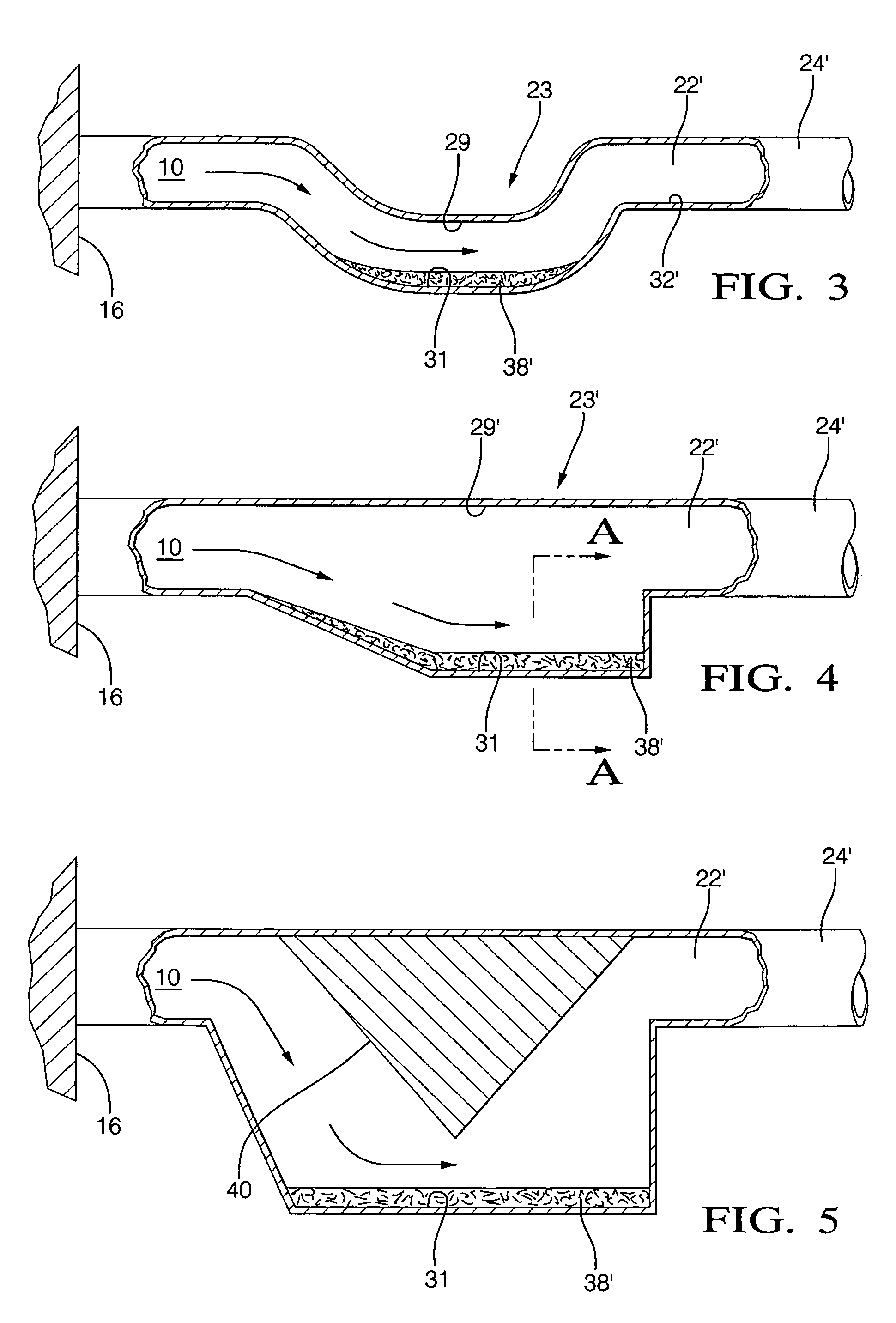
[0039] Referring to FIG. 3, upstream flow of HC vapors 10 from engine 16 is directed downwards into portion 23 by the gravitational relationship of portion 23 to main intake passageway 22′. This flow direction urges the HC vapors toward medium 38′ which is distributed along a region of bottom wall 31. In contrast to prior art embodiment 01, the entire flow of air and HC vapors in passageway 22′ is made available to the medium. Preferably the cross-sectional area of portion 23 is sized to accommodate the thickness of medium 38′ such that portion 23 presents no significant restriction to the flow of air to the engine during operation thereof.

[0040] Referring to FIG. 4, the upper wall 29′ of portion 23′ is continuous with the upper wall of main intake passageway 22′; this configuration provides a straighter path for intake air while also providing a low region for accumulation of HC vapors but at a cost of less direction for the vapors when the engine is off. This configuration is appl...

embodiment 23

[0046] The medium configurations 38-1,38-2,38-3 are shown for simplicity in respect to embodiment 23′ shown in FIG. 4 but of course these medium configurations are equally applicable to all configurations of trap portions 23, 23′, 23″.

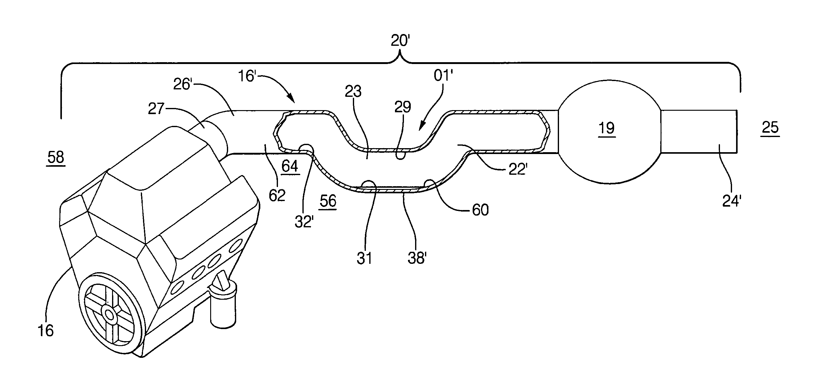
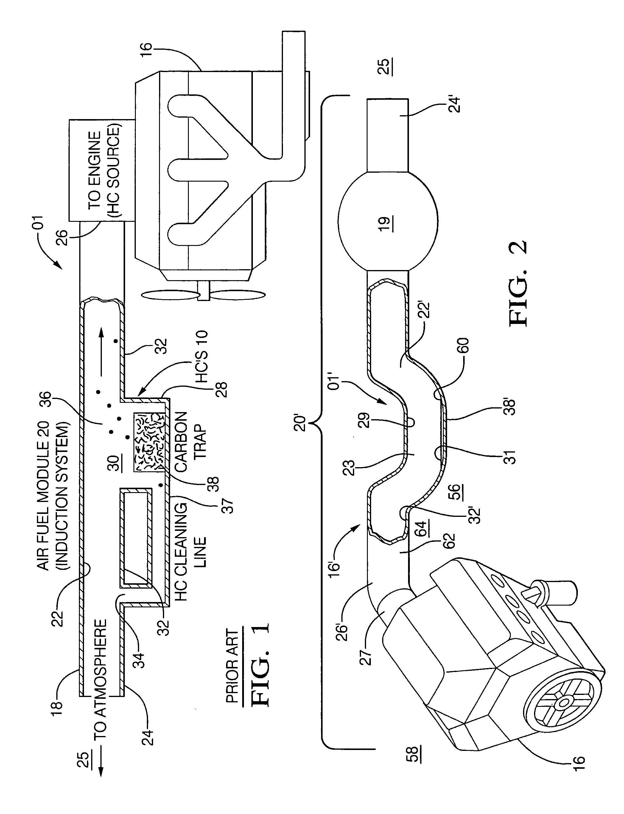
[0047] Referring again to FIG. 2, preferably passageway 23 and medium 38′ are located in an area 56 of the engine compartment 58 to conduct the hotter temperatures of the gases contained in downstream end 26′ of intake passageway 22′ away from medium 38′ during periods of engine shutdown such that temperature 60 of medium 38′ is lower than temperature 62 of the gases within passageway 22′ to thereby improve the efficiency of hydrocarbon adsorption. FIG. 9 shows embodiment 38-3′ wherein finned heat sink projections 64 extend from bottom wall 31 and / or side walls 42 to transfer heat away from sheet 54 and toward lower temperature 64 in area 56. It is understood that the use of finned heat sink projections 64 for improving the efficiency of cooling is equ...


PUM


Abstract

An air intake hydrocarbon vapor trap system for an internal combustion engine comprising a hydrocarbon-adsorptive medium, such as activated carbon, disposed in a gravitationally low point in the intake air flow passageway between the entrance to the system and the engine. The intake duct itself is configured to provide the low region for disposition of the medium. The medium is thereby fully exposed to the flow of gases through the duct and is not confined to a separate walled pit as in the prior art. The medium, for example, activated carbon, may be provided in any of several forms, such as in a pelletized bed, a rigid formed structure, or as a “sheet” or “paper.” Preferably, the medium is disposed in the engine compartment to optimally transfer heat away from it during engine shut-down.

Description

TECHNICAL FIELD [0001] The present invention relates to internal combustion engines; more particularly, to devices for preventing escape of hydrocarbon vapors from internal combustion engines; and most particularly, to a hydrocarbon vapor trap disposed in the air intake portions of such an engine for adsorbing vapors when the engine is shut down. BACKGROUND OF THE INVENTION [0002] Gasoline-fueled motor vehicles have numerous sites from which gasoline hydrocarbons (HC) can evaporate into the atmosphere. Atmospheric HC is a major contributor to smog formation; thus, there is great interest in providing means for reducing or preventing inadvertent escape of HC vapors from vehicles and their internal combustion engines. [0003] The control of HC vapors escaping into the atmosphere is also the subject of substantial state and federal regulations. For example, The California Air Resources Board (CARB) has adopted stringent vapor emissions regulations, known generally as Low Emission Vehicl...

Claims


Application Information

Patent Timeline
IPC IPC(8): F02M33/04
CPCF02M25/08F02M35/024F02M35/10268F02M35/10222F02M35/10124
Inventor BURKE, DAVID H.TURNER, KENNETH W.MAHAN, STEPHEN T.
Owner DELPHI TECH INC
Learn More