Plasma processing apparatus

a processing apparatus and plasma technology, applied in the direction of coatings, chemical vapor deposition coatings, electric discharge tubes, etc., can solve the problems of reducing the efficiency of mounting and dismounting operations, prolonging the operation time, and still has some drawbacks, so as to enhance the operation efficiency of the plasma processing apparatus, facilitate operation, and small installation area

Inactive Publication Date: 2006-03-16
HITACHI HIGH-TECH CORP
View PDF4 Cites 18 Cited by
  • Summary
  • Abstract
  • Description
  • Claims
  • Application Information

AI Technical Summary

Benefits of technology

[0021] According to the present invention, it is possible to provide the plasma processing apparatus which is small-sized and requires a small installation area.
[0022] Further, according to the present invention, it is possible to provide the plasma processing apparatus which can easily perform the operations such as the maintenance and mounting and dismounting of the equipment.
[0023] Still further, it is also possible to provide the plasma processing apparatus which can enhance the operation efficiency of the plasma processing apparatus.

Problems solved by technology

The above-mentioned related prior art, however, has failed to pay the sufficient consideration on following points and hence, the related art still has some drawbacks.
Accordingly, the efficiency of mounting and dismounting operation and maintenance operation is lowered, thus leading to the prolongation of the operation time.
Eventually, there has been a drawback that a non-operative period that the apparatus is not operated is prolonged and hence, the operation efficiency of the apparatus is lowered and the manufacturing cost is increased.
That is, in mounting or dismounting the equipment in the processing chambers, no consideration has been take with respect to the constitution which enhances the operation efficiently other than positioning, thus giving rise to a drawback that the operation time is prolonged and hence, the operation efficiency of the apparatus is deteriorated.

Method used


Image

  • Plasma processing apparatus
  • Plasma processing apparatus
  • Plasma processing apparatus

Examples


Embodiment Construction

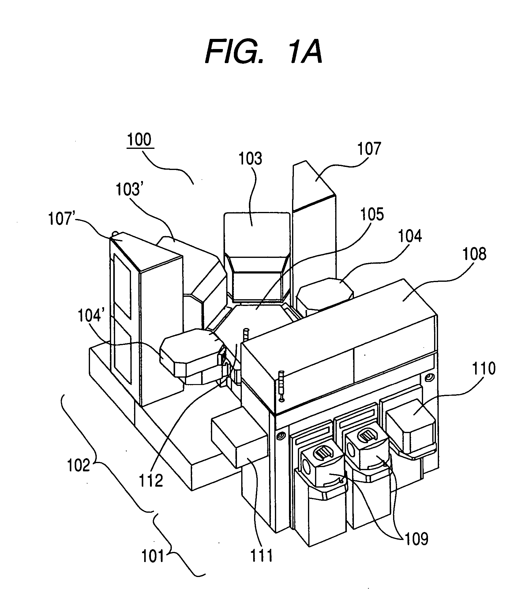
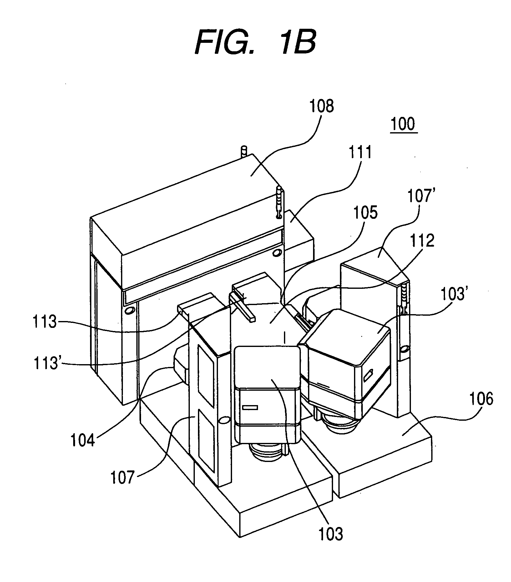
[0048] Preferred embodiments of the present invention are described in detail in conjunction with attached drawings hereinafter. FIGS. 1A and 1B are perspective views showing the whole constitution of a plasma processing apparatus according to an embodiment of the present invention, in which FIG. 1A is a view as viewed from the front and FIG. 1B is a perspective view as viewed from the back.

[0049] In these drawings, the plasma processing apparatus 100 of this embodiment is roughly classified into two blocks, that is, front and rear blocks. The front side of an apparatus body 100 constitutes an atmospheric-pressure-side block 101 which enables the transporting of a wafer supplied to the apparatus into a chamber whose pressure is reduced under an atmospheric pressure and the supplying of the wafer into the processing chamber. Behind the apparatus body 100, the process block 102 is arranged. The process block 102 includes processing units 103, 103′ and 104, 104′ which have processing ...


PUM

PropertyMeasurementUnit
pressureaaaaaaaaaa
temperatureaaaaaaaaaa
circumferenceaaaaaaaaaa

Abstract

The present invention provides a plasma processing apparatus for processing a sample on a sample stand in a vacuum container whose inside pressure is reduced, with a plasma generated in an upper space above the sample stand. The apparatus comprises: an electric discharge chamber disposed in the vacuum container and above the sample stand, and having a discharge-chamber sidewall surrounding the upper space; a vacuum chamber disposed in the vacuum container and below the electric discharge chamber, and in communication with the electric discharge chamber; a vacuum-chamber sidewall disposed inside the vacuum container to surround the sample stand, and constituting a side surface of the vacuum chamber; a first temperature regulator disposed outside the discharge-chamber sidewall to adjust a temperature of the discharge-chamber sidewall; and a second temperature regulator controlling a temperature of the vacuum-chamber sidewall to a value lower than the temperature of the discharge-chamber sidewall.

Description

CLAIM OF PRIORITY [0001] The present application claims priority from Japanese Application JP 2004-263722 filed on Sep. 10, 2004, the content of which is hereby incorporated by reference into this application. BACKGROUND OF THE INVENTION [0002] The present invention relates to a plasma processing apparatus which processes an object to be processed in the inside of pressure-reduced apparatus, and more particularly to an apparatus which processes, by using plasma, a semiconductor substrate (wafer) which constitutes the object to be processed in the inside of the apparatus. [0003] In the above-mentioned apparatus, particularly in the apparatus which processes the object to be processed in the inside of the pressure-reduced apparatus, along with a demand for the finer processing and the more accurate processing, there has been a demand for the enhancement of the efficiency of the processing of the substrate which constitutes the object to be processed. Accordingly, in recent years, a mu...

Claims


Application Information

Patent Timeline
Patent Type & Authority Applications(United States)
IPC IPC(8): C23F1/00C23C16/00
CPCH01J37/32522H01L21/67248H01L21/67196H01L21/6719
Inventor MAKINO, AKITAKAKIHARA, HIDEKITAUCHI, SUSUMUYATOMI, MINORUNAGAYASU, NOBUO
Owner HITACHI HIGH-TECH CORP
Why Eureka
Try Eureka