Adjustable Support Apparatus for Machinery

a technology of adjustable support and machinery, which is applied in the direction of mechanical equipment, machine supports, other domestic objects, etc., can solve the problem of limited load capacity

Inactive Publication Date: 2006-03-16
ROWAN ROBERT L JR +1
View PDF10 Cites 17 Cited by
  • Summary
  • Abstract
  • Description
  • Claims
  • Application Information

AI Technical Summary

Benefits of technology

[0013] In a further embodiment, the apparatus can include a lock engaged between the second and third members for maintaining the rotational alignment between the members. In one example, the lock can include a plurality of serrations formed on the spiraling faces of the second and third members. In another example, the lock can include a cap screw threaded transversely through one of the members and having a distal end engaging the other member to maintain the rotational alignment between the members. In yet another example, the lock can include a dowel pin or cap screw positioned axially through one of the members and having a distal end positioning axially through a portion of the other member to maintain the rotational alignment between the members.

Problems solved by technology

The main problem with the screw jack support 50 is that the load capacity is limited by the shear strength of the screw threads 55 that provide the vertical alignment for the support 50.

Method used


Image

  • Adjustable Support Apparatus for Machinery
  • Adjustable Support Apparatus for Machinery
  • Adjustable Support Apparatus for Machinery

Examples


Embodiment Construction

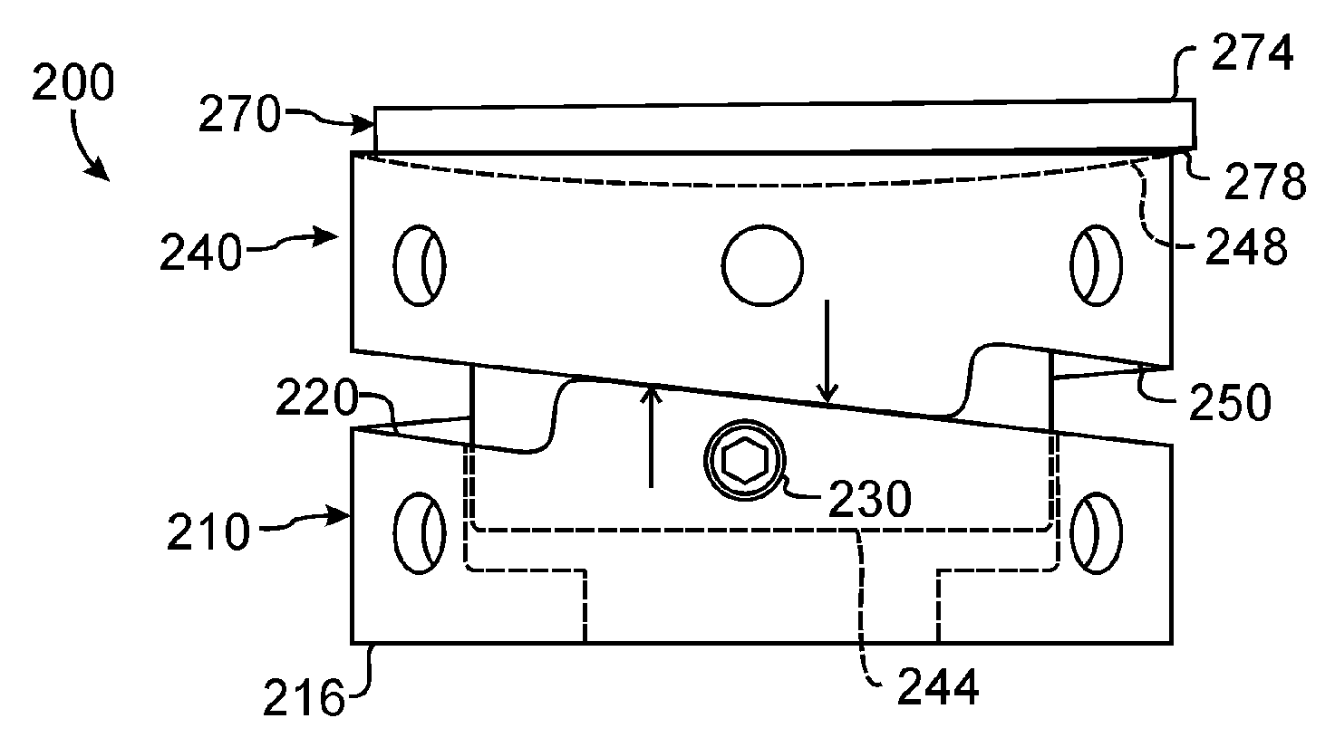
[0037] Referring to FIGS. 3A-3B, a laterally adjustable support system 100 is shown positioned between a motor foot 12 and a machinery skid 14. FIG. 3A shows a side view in partial cross-section, while FIG. 3B shows a top view without the motor foot present. To hold the foot 12 to the skid 14, a hold down or anchor bolt 110 passes through the foot 12, a laterally adjustable support 130A, and the skid 14. A jack screw 112 is threaded through the foot 12 and its distal end contacts the skid 14. Rotation of the jack screw 112 allows the orientation of the foot 12 to be adjusted relative to the skid 14. Several of these arrangements of hold down bolts 110, supports 130A, and jack screws 112 are used on a motor, and the jack screws 112 can be adjusted to level the motor. Conversely, any equipment being driven by a motor or any prime mover, such as a pump or compressor, can be similarly supported. Other potential applications for the support 130A include diesel engine generator sets and m...


PUM


Abstract

An apparatus for supporting an axial load between first and second planes with an axial dimension therebetween includes first, second, and third members. The first member has a planar face on one end engaging the first plane and has a spherical face on the other end. The second member has a spiraling face on one end and has a spherical face on another end. The spherical face engaging the spherical face of the first member so that the first and second spherical faces maintain substantial contact for transferring the axial load between the first and second planes whether the planes are parallel or non-parallel. The third member has a spiraling face on one end and has a planar face on another end. The planar face engages the second plane. The spiraling face engages the spiraling face of the second member. The axial dimension of the second and third members can be adjusted when at least one is rotated.

Description

CROSS-REFERENCE TO RELATED APPLICATION [0001] This application claims the benefit of U.S. Provisional Application Ser. No. 60 / 610,348, filed Sep. 16, 2004, which is incorporated herein by reference.FIELD OF THE DISCLOSURE [0002] The subject matter of the present disclosure generally relates to a support for machinery and more particularly relates to an adjustable support apparatus for machinery that provides both support and vertical alignment capability with or without an associated anchor bolt. BACKGROUND OF THE DISCLOSURE [0003] Various types of machinery support systems have been around for years. Examples of some of prior art machinery support systems include U.S. Pat. No. 5,110,082 “Adjustable Apparatus for Supporting Machinery or Other Load” and U.S. Pat. No. 5,016,338 “Method for Adjusting the Vertical Position of a Frame on a Foundation.”[0004]FIG. 1A shows the frame 12 of a machine 10 anchored to and supported by a foundation 14, which is typically constructed from concret...

Claims


Application Information

Patent Timeline
Patent Type & Authority Applications(United States)
IPC IPC(8): F16M11/00F16M9/00
CPCF16M7/00
Inventor ROWAN, ROBERT L. JR.ROWAN, CHARLES L.
Owner ROWAN ROBERT L JR
Why Eureka
Try Eureka