
Voltage supply circuit and method for starting a circuit arrangement

Inactive Publication Date: 2006-03-16
INFINEON TECH AG +1
View PDF13 Cites 2 Cited by
  • Summary
  • Abstract
  • Description
  • Claims
  • Application Information

AI Technical Summary

Benefits of technology

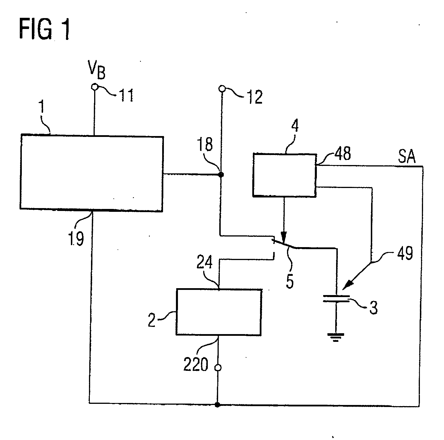
[0011] According to one or more aspects of the present invention, the effect achieved by an exemplary arrangement is that a circuit whose operation requires a charged charge store can arrive at its active operating state very quickly. This is achieved by the regulator circuit, which is suitably designed for the charging process for the charge store. The quantity of charge or the voltage on the charge store which is required for the circuit to operate can be output much more quickly by the regulator circuit, on account of a higher current-carrying capacity, than the circuit with which the charge store is associated.
[0016] According to one or more aspects of the present invention, an exemplary method allows a significant reduction in the duration of an activation operation or in the duration of a startup operation. At the same time, the power consumption in a power-saving mode is reduced, since the switching elements and, in particular, also the charge stores which are not required are isolated from a residual power supply (e.g., a battery).
[0018] According to one or more aspects of the present invention, an exemplary control circuit is coupled to the regulator circuit and / or to the circuit. It is designed to output signals which put one or more circuits connected to it into a desired operating state. This means that the control circuit is able to change the circuit from the inactive operating state to the active operating state, for example. This promotes error-free operation of the circuit, since in a suitable embodiment the control circuit is designed to output an activation signal to the circuit at a time at which the charge store is coupled to the circuit.
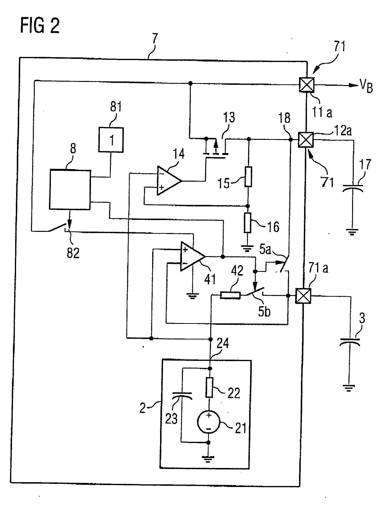
[0022] According to one or more aspects of the present invention, the regulator circuit and the circuit are in the form of integrated circuits in a semiconductor body. This is particularly expedient when the semiconductor body has further integrated circuits which are supplied by being connected to the output of the regulator circuit. In one example, the charge store is arranged outside of the semiconductor body. This is advantageous when charge stores having a very large capacitance and therefore also a relatively long charging time are provided. Charge stores with a very large capacitance can be produced outside of the semiconductor body so as to save surface area. Inputs and outputs of the regulator circuit are provided by contact pads produced on the surface of the semiconductor body.
[0023] According to one or more aspects of the present invention, the control circuit comprises a signal input for disconnection. This signal input is connected to the circuit, with the circuit in the active operating state being designed to output a disconnection signal to the control circuit. This reduces the power consumption of the control circuit, since said control circuit is no longer required during the active operating state.

Problems solved by technology

This lowers the overall power consumption and extends the life of the battery.
However, leakage currents in the capacitor result in a continuous power consumption even during the power-saving state, which means that such a design is not entirely desirable.
This is often a problem, however, since low-noise circuit elements are generally designed for relatively small currents, which can significantly prolong the charging time.

Method used


Image

  • Voltage supply circuit and method for starting a circuit arrangement
  • Voltage supply circuit and method for starting a circuit arrangement
  • Voltage supply circuit and method for starting a circuit arrangement

Examples


Embodiment Construction

[0029] One or more aspects of the present invention will now be described with reference to the drawing figures, wherein like reference numerals are used to refer to like elements throughout. It should be understood that the drawing figures and following descriptions are merely illustrative and that they should not be taken in a limiting sense. In the following description, for purposes of explanation, numerous specific details are set forth in order to provide a thorough understanding of the present invention. It will be evident to one skilled in the art, however, that the present invention may be practiced without these specific details. Thus, it will be appreciated that variations of the illustrated systems and methods apart from those illustrated and described herein may exist and that such variations are deemed as falling within the scope of the present invention and the appended claims.

[0030]FIG. 1 illustrates a first exemplary embodiment of a circuit arrangement according to...


PUM


Abstract

One or more aspects of the present invention pertain to a voltage supply circuit arrangement. In one example, an arrangement comprises a voltage regulator designed to output a regulated voltage, derived from a first supply voltage applied to a supply input. An additional circuit component is also included that has inactive and active operating states, wherein the circuit has a functional action in the active operating state. In the active operating state, a charge store is part of the circuit. In the inactive operating state, the circuit is coupled to the output of the voltage regulator component, where the voltage regulator component is designed to output a charging current to the charge store. In addition, a control circuit is provided which is designed to evaluate an electrical parameter for the charge store. On the basis of the evaluation, the charge store is coupled to the circuit. As a result, the circuit adopts the active operating state.

Description

REFERENCE TO RELATED APPLICATIONS [0001] This application claims the benefit of the priority date of German application DE 10 2004 041 920.5, filed on Aug. 30, 2004, the contents of which are herein incorporated by reference in their entirety. FIELD OF THE INVENTION [0002] One or more aspects of the present invention relate to a voltage supply circuit, and a method for starting up a circuit arrangement. BACKGROUND OF THE INVENTION [0003] The desire for a high level of mobility by users makes it necessary for electronic devices, such as mobile radios, PDAs (personal digital assistants), portable computers (e.g., laptops, notebooks) and / or other mobile devices, for example, to be powered by one or more batteries that meet current and / or voltage needs. The users' desire for small, lightweight devices that can be easily carried is leading to a reduction in the size of batteries and hence also in the amount of power available. Accordingly, to extend the life of mobile devices, the device...

Claims


Application Information

Patent Timeline
IPC IPC(8): H02J7/00
CPCG05F1/56
Inventor FABBRO, SIMONE
Owner INFINEON TECH AG
Learn More