
Method for the manufacturing of a capacitive pressure sensor, and a capacitive pressure sensor

Active Publication Date: 2005-11-10
MURATA MFG CO LTD
View PDF8 Cites 4 Cited by
  • Summary
  • Abstract
  • Description
  • Claims
  • Application Information

AI Technical Summary

Benefits of technology

[0019] The object of the invention is an improved method of manufacturing a capacitive pressure sensor, and an improved capacitive pressure sensor. By means of the present invention, silicon wafer surface area is saved and it is suitable, in particular, for use in small capacitive pressure sensor solutions.

Problems solved by technology

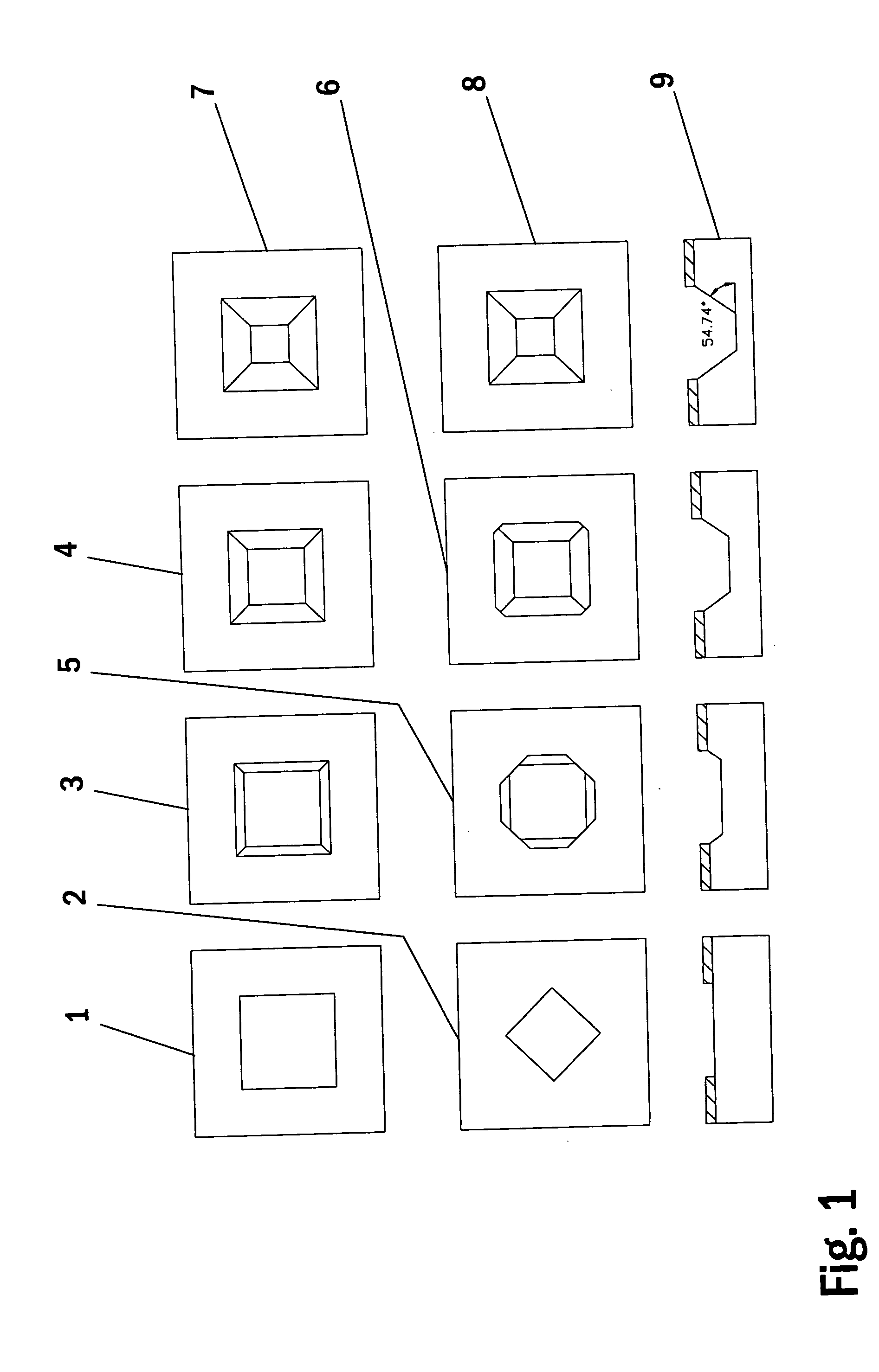
Its biggest drawback is the area occupied by structures defined by the extremely slowly etching sloping crystal planes {111}.
On the other hand, the geometry of the structures is, limited by the crystal structure and there are a limited number of basic structures.
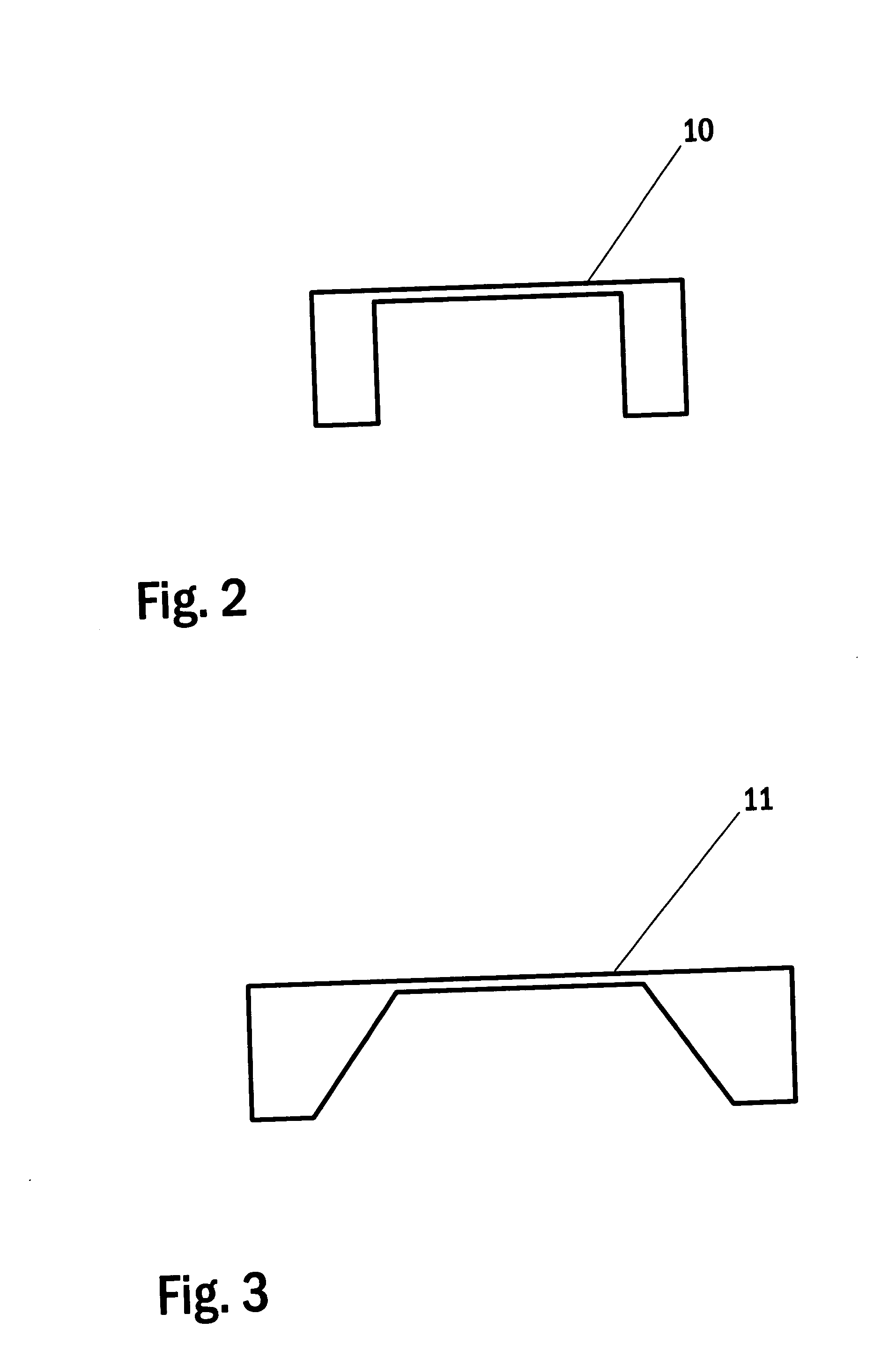
However, the ideal structure 10 depicted in the figure cannot be produced by wet etching into silicon (100).
The most severe drawback of anisotropic wet etching is the surface area occupied by structures defined by the sloping extremely slowly etching crystal planes {111}.
Often the problem of surface area loss is solved by using dry etching DRIE (Deep Reactive Ion Etching), but the evenness of the depth of the etching is not nearly so well controlled as in wet etching.
In the structure of a pressure sensor according to prior art, a problem is the surface area occupied by the structures of the, in anisotropic wet etching of silicon, extremely slowly etching sloping crystal planes {111}.

Method used


Image

  • Method for the manufacturing of a capacitive pressure sensor, and a capacitive pressure sensor
  • Method for the manufacturing of a capacitive pressure sensor, and a capacitive pressure sensor
  • Method for the manufacturing of a capacitive pressure sensor, and a capacitive pressure sensor

Examples


Embodiment Construction

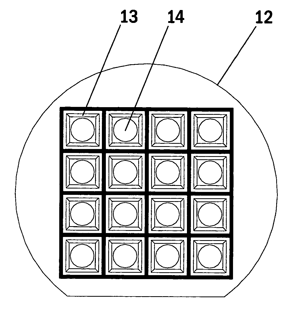
[0041]FIG. 5 shows a silicon wafer of type (100) according to the present invention, in which wafer pressure sensor membrane structures have been produced by anisotropic wet etching. Sixteen diamond shaped etched areas are depicted in the silicon wafer 15 according to the present invention. In the figure, circles indicate the area 17 of the flexible membrane portion of the pressure sensor, which area is patterned on the back surface of the membrane. The cutting lines for the pressure sensor elements are drawn with heavy black lines. In the solution according to the present invention, the orientation of the cutting is turned by 45 degrees in relation to the direction 110>.

[0042] In the silicon wafer of direction (100), according to the present invention, diamond shaped membrane areas 17 are produced by wet etching, in which areas the crystal planes {111} will be located at the corners of the wet etched membrane well. By means of the present invention, a large portion of the surface ...


PUM

PropertyMeasurementUnit
Shapeaaaaaaaaaa
Areaaaaaaaaaaa
Sensitivityaaaaaaaaaa

Abstract

The invention relates to measuring devices for the measuring of pressure, and more specifically to capacitive pressure sensors. The silicon crystal planes {111} are located at the corners of a wet etched membrane well of a pressure sensor element according to the present invention. An object of the invention is to provide an improved method of manufacturing a capacitive pressure sensor, and a capacitive pressure sensor suitable for use, in particular, in small capacitive pressure sensor solutions.

Description

FIELD OF THE INVENTION [0001] The invention relates to measuring devices used in the measuring of pressure, and more specifically to capacitive pressure sensors. The object of the invention is to provide an improved method for the manufacturing of a capacitive pressure sensor and a capacitive pressure sensor suitable, in particular, for use in small capacitive pressure sensor solutions. BACKGROUND OF THE INVENTION [0002] The principle of measuring based on a capacitive pressure sensor has proved to be a simple and reliable way of measuring pressure. Capacitance measuring is based on a change in the gap between two surfaces of a pair of electrodes in the sensor. The capacitance between the surfaces, i.e. the storage capacity of electric charge, is a function of the area of the surfaces and the distance between the surfaces. Capacitance measuring can be used even at fairly low ranges of pressure. [0003] The basis for the structure of small capacitive pressure sensors is a thin-film st...

Claims


Application Information

Patent Timeline
IPC IPC(8): G01L9/00
CPCG01L9/0073Y10T29/41Y10T29/413Y10T29/49
Inventor RUOHIO, JAAKKOASTROM, RIIKKA
Owner MURATA MFG CO LTD
Learn More