Capacitive humidity sensor

a humidity sensor and capacitive technology, applied in the field of capacitive humidity sensors, can solve the problems of difficult to reduce the whole size of sensors including circuit sections, and high cost of semiconductor substrates, so as to reduce the size and low cost

Inactive Publication Date: 2006-03-16
DENSO CORP
View PDF11 Cites 29 Cited by
  • Summary
  • Abstract
  • Description
  • Claims
  • Application Information

AI Technical Summary

Benefits of technology

[0007] In view of the above-described problem, it is an object of the present invention to provide a capacitive humidity sensor including a sensor section, which has a reduced size while being manufactured in low cost.
[0008] A capacitive humidity sensor of an embodiment of the present invention includes a printed circuit board having an insulating substrate on which a circuit section is disposed, a pair of electrodes disposed on a surface of the insulating substrate, opposite from each other with a space, a humidity sensitive layer disposed on the insulating substrate to cover the electrodes and the surface of the insulating substrate between the electrodes, and a wiring section provided in the insulating substrate. In this sensor, the humidity sensitive layer has a relative permittivity which changes in response to a humidity, the electrodes and the circuit section are electrically connected through the wiring section, and the circuit section performs a signal processing of a capacitance change between the electrodes. Accordingly, the electrodes, the circuit section and the wiring section can be integrated with the insulating substrate, and the whole size of the sensor including the circuit section can be reduced.
[0009] Further the electrodes, the humidity sensitive layer and the circuit section can be formed on the insulating substrate using a common manufacturing technique (e.g., patterning of conductive foil or screening printing) for a printed circuit board. Therefore, the electrodes and the humidity sensitive layer can be easily integrated with the circuit section, and the sensor can be manufactured at low cost.
[0011] Furthermore, the wiring section can be disposed inside the insulating substrate to penetrate through the insulating substrate. As an example, the insulating substrate has a via hole, and the wiring section has a connection material filled in the via hole. Alternatively, the insulating substrate has a through hole, and the wiring section has an electrical conductor arranged on a wall surface for defining the through hole. Accordingly, the wiring section is hardly affected by external force. In addition, reliability of electrical connection between the electrodes and the circuit section can be improved, as compared with a case where the electrodes and the circuit section are connected through bonding wires.

Problems solved by technology

Therefore, it is difficult to reduce the whole size of the sensor including the circuit section.
Therefore, complex process and expensive equipment are required to manufacture the sensor in addition to high cost of a semiconductor substrate.
Accordingly, the manufacturing cost of the sensor increases.

Method used


Image

  • Capacitive humidity sensor
  • Capacitive humidity sensor
  • Capacitive humidity sensor

Examples


first embodiment

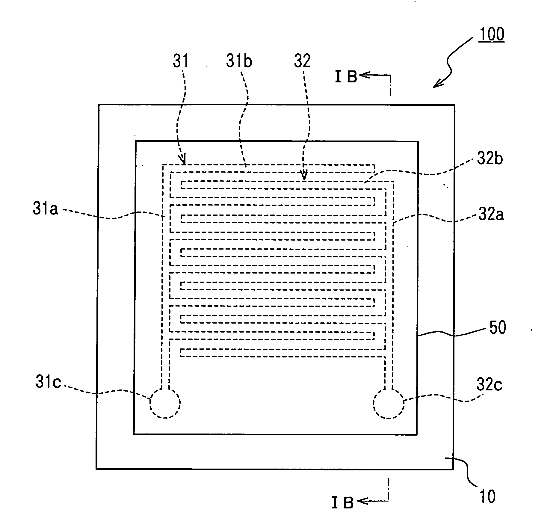
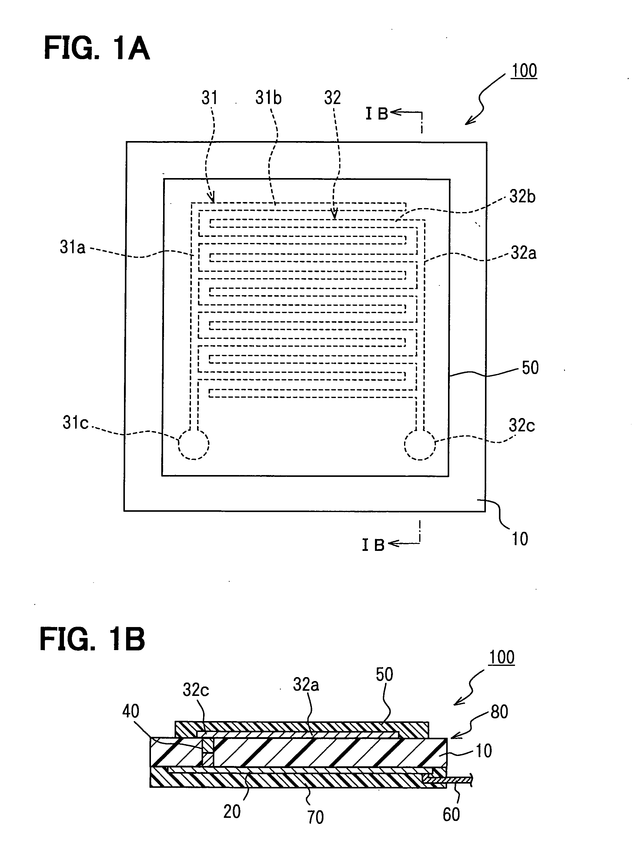
[0017] A capacitive humidity sensor 100 according to the first embodiment of the present invention is shown in FIGS. 1A and 1B. In this embodiment, an electrical insulating material commonly used for a printed circuit board (PCB) is typically used as an insulating substrate 10. As an example, in the sensor 100, the insulating substrate 10 is formed from multiple layers (e.g., two layers in this embodiment) of thermoplastic resin films, which are made of liquid crystal polymer (LCP) and laminated together under pressure and heat.

[0018] A circuit section 20 is formed on one surface of the insulating substrate 10 as a part of a circuit pattern of a printed circuit board 80. The circuit section 20 performs a signal processing of a capacitance change between a pair of electrodes 31, 32. The circuit section 20 is composed of the part of the circuit pattern and electronic components (not shown) mounted thereon. In order to form the circuit section 20, conductive foil is bonded to a surfac...

second embodiment

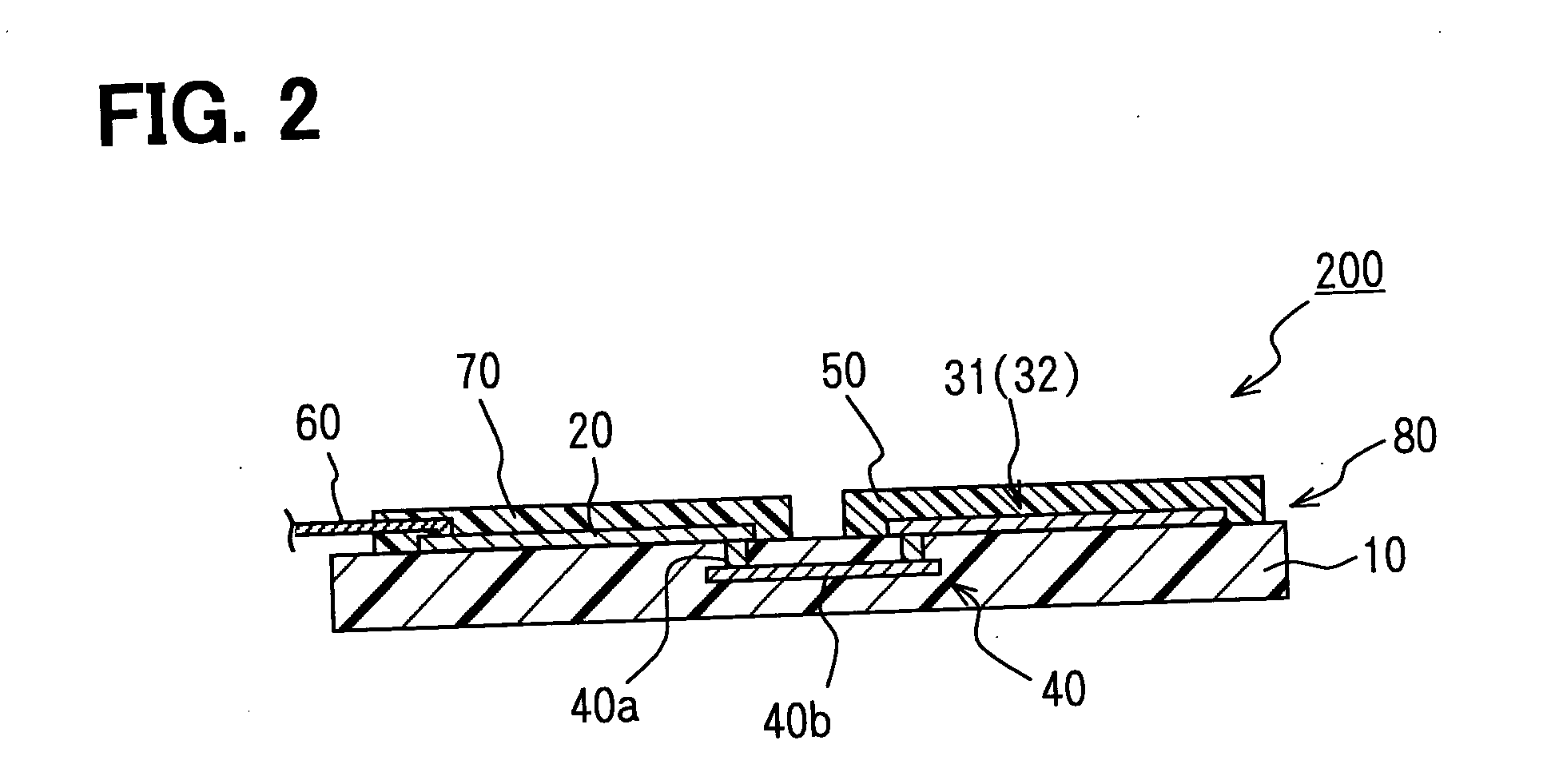
[0035] A capacitive humidity sensor 200 of the second embodiment will be now described with reference to FIG. 2.

[0036] In the sensor 100 of the above-described first embodiment, the electrodes 31, 32 and the circuit section 20 are formed on different surfaces of the insulating substrate 10. In contrast, in the capacitive humidity sensor 200 of the second embodiment, electrodes 31, 32 and a circuit section 20 are formed on the same surface of an insulating substrate 10.

[0037] In the sensor 200, the electrodes 31, 32 and the circuit section 20 are electrically connected through wiring sections 40 formed in the insulating substrate 10. The electrodes 31, 32, a humidity sensitive layer 50, the circuit section 20 and the wiring sections 40 are integrated to the insulating substrate 10. Therefore, the whole size of the sensor 200 including the circuit section 20 can be effectively reduced.

[0038] As shown in FIG. 2, a connection material is filled in via holes to form connection portion...


PUM


Abstract

A capacitive humidity sensor includes a printed circuit board having an insulating substrate on which a circuit section is formed, a pair of electrodes formed on a surface of the insulating substrate to be opposite from each other with a space, and a humidity sensitive layer formed on the insulating substrate to cover the electrodes and the surface of the insulating substrate between the pair of electrodes. The relative permittivity of the humidity sensitive layer changes in response to humidity, and the circuit section performs a signal processing of a capacitance change between the electrodes. Furthermore, the electrodes and the circuit section are electrically connected through a wiring section formed in the insulating substrate.

Description

CROSS REFERENCE TO RELATED APPLICATION [0001] This application is based on Japanese Patent Application No. 2004-267206 filed on Sep. 14, 2004, the disclosure of which is incorporated herein by reference. FIELD OF THE INVENTION [0002] The present invention relates to a capacitive humidity sensor having a humidity sensitive layer. BACKGROUND OF THE INVENTION [0003] A capacitive humidity sensor, disclosed in JP-U-5-23124, has a humidity sensitive layer interposed between a pair of electrodes. Relative permittivity of the humidity sensitive layer is changed in response to humidity. [0004] In this sensor, the electrodes are arranged opposite to each other on a surface of an insulating substrate, and the humidity sensitive layer (a dielectric material) is disposed on the electrodes. Further, a circuit section such as a signal processing circuit for a capacitance change between the electrodes is disposed in a substrate separated from the insulating substrate. Therefore, the electrodes are ...

Claims


Application Information

Patent Timeline
Patent Type & Authority Applications(United States)
IPC IPC(8): H01C10/10
CPCG01N27/225
Inventor TANIDA, KATSUNORI
Owner DENSO CORP
Why Eureka
Try Eureka