[0020] This aspect of the invention assumes that in the case of typical larger liquid
crystal display devices, the components involved are also larger and heavier, such that twisting and
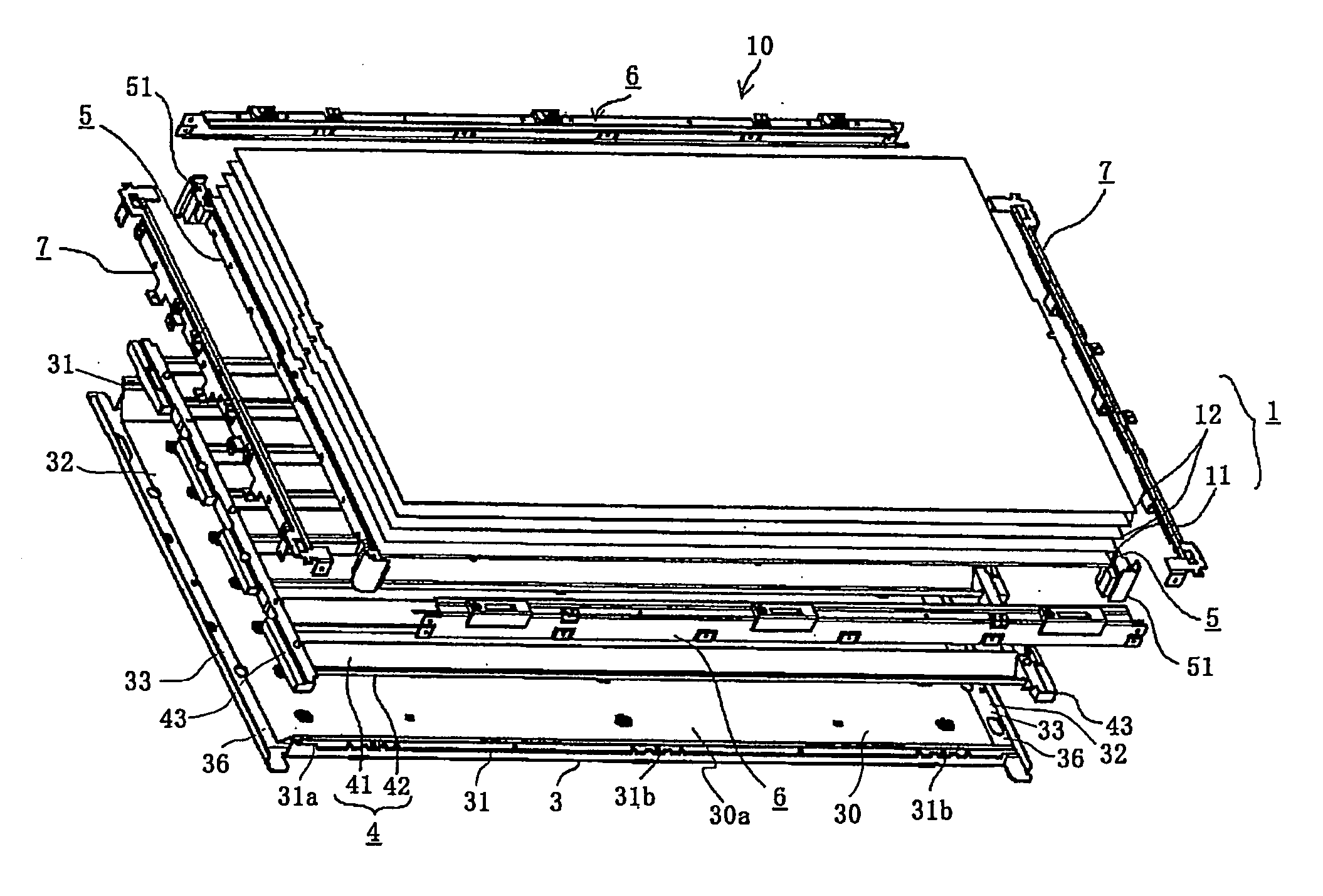
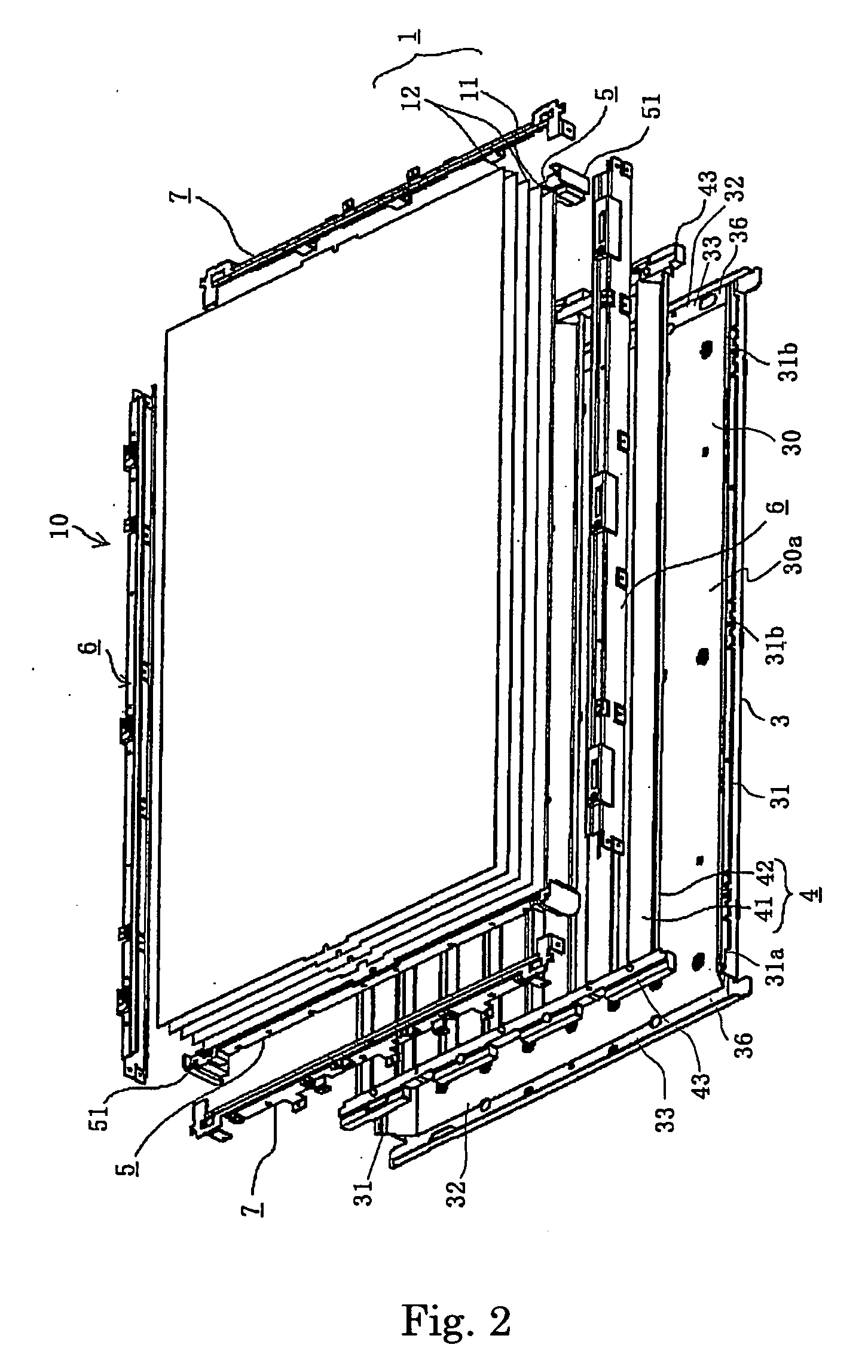
distortion thereof and the like easily occur in a normal frame (which is a previously integrally formed frame), during vibration and the like, since the frame cannot firmly hold the components together, and therefore the possibility of occurrence of a large slippage and the like arises in the optical member. However, the use of the above-described reinforcing frames makes it possible to firmly assemble the optical member, the backlight unit and the like to the main body case, despite being large and heavy. In addition, since the divided reinforcing frames are joined directly, providing for corner members with which to connect them is unnecessary. Further, even though the frame consists of a plurality of frames, the unit price of each component is lower while enhancing dimensional accuracy thereof, thereby ensuring lower cost and robustness.
[0022] In addition, the gaps forming in the joints between components are sealed to prevent the leakage of light and the intrusion of foreign objects such as
dirt and dust.
[0024] Further, since the transparent and thick reinforcing plate is provided at the opening of the main body case 3 and affixed to the reinforcing frames, the reinforcing plate does not become shaky, promoting robustness of the
lighting system, and matching with the liquid
crystal display panel becomes better.
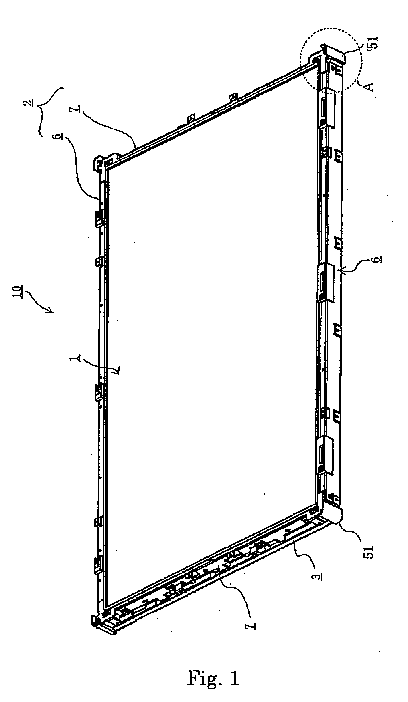
[0026] Likewise, in this aspect of the invention, by constituting the outer frame in the shape of a picture frame covering the periphery of the liquid
crystal display panel, in divided frames, no gap is required to be provided between the outer frame and the supporting means for affixing the same, and thus stress-causing
distortion in the outer frame will not occur when it is affixed to the supporting means by screws and the like. In this manner, any
adverse effect to the quality of display of the display panel due to the occurrence of stress may be avoided. Further, when the outer frame is formed by die-
cutting a plate material from
metal plate material, the amount of
waste material is drastically reduced, thereby
cutting production cost. Additionally, when the liquid
crystal display panel is constituted in rectangular form, different plate materials of varied sizes can be used to produce the upper and lower outer frames and the right and left outer frames, and thus the amount of
waste material after die-
cutting the plate material is reduced, and production cost can thus be scaled down further. Further, still, by connecting the outer frames to each other after being affixed to the supporting means, the outer frames and the supporting means are securely fixed without any clearance, as to prevent the frames from being deformed due to the presence of such clearance.
[0028] Further still, it is preferable that the side walls of the main body case and the side walls of the middle member be made to form a chamber of a predetermined size by creating a periphery for each side wall, housing the backlight unit in the chamber, and installing the outer periphery of the
assembly to the reinforcing frame after providing for
peripheral ends for the optical member on each side wall, so that the different components of the liquid
crystal display device such as the main body case can be solidly constructed and the optical member can be firmly affixed to the main body case. In this manner, it would be possible to remove the backlight unit easily from the
assembly without dismantling the optical member on purpose.

