Apodized diffraction grating with improved dynamic range

a diffraction grating and dynamic range technology, applied in the field of diffraction gratings with improved dynamic range, can solve the problems of many conventional spectral filters having limited transmission width and rejection shape, and the diffraction efficiency of the grating cannot be easily used with a multi-wavelength input light beam, etc., and achieve the effect of varying the diffraction efficiency of the grating

Inactive Publication Date: 2006-03-16
AGILENT TECH INC
View PDF6 Cites 55 Cited by
  • Summary
  • Abstract
  • Description
  • Claims
  • Application Information

AI Technical Summary

Benefits of technology

[0016] An optical diffraction grating includes a substrate and a diffraction surface comprising, for example, diffraction grooves. The diffraction grating has a spatially varying diffraction efficiency which increases or decreases as a function of distance from a reference location at which an incident light beam i...

Problems solved by technology

However, such dense packing requires precise combination, separation, and other handling of these light beams.
However, as shown in FIG. 1B, this not always possible.
In general, the diffraction grating described in FIG. 1A cannot readily be used with a multi-wavelength input light b...

Method used


Image

  • Apodized diffraction grating with improved dynamic range
  • Apodized diffraction grating with improved dynamic range
  • Apodized diffraction grating with improved dynamic range

Examples


Embodiment Construction

[0034] In the following detailed description, reference is made to the accompanying drawing figures which form a part hereof, and which show by way of illustration specific embodiments of the invention. Other embodiments may be utilized, and structural, electrical, as well as procedural changes may be made without departing from the scope of the present invention.

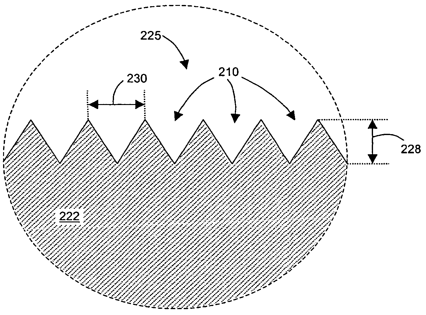
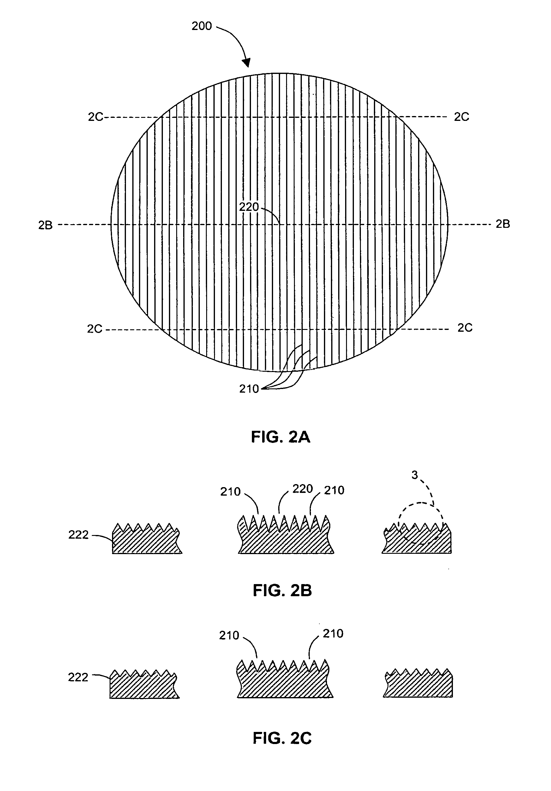
[0035] With reference to FIG. 2, diffraction grating 200 may be broadly described as having a spatially varying diffraction efficiency such that the diffraction efficiency (that is, the amount of light diffracted at a given order) of the grating changes as a function of displacement from a reference location on the grating. The spatially varying diffraction efficiency of the diffraction grating of the invention contrasts conventional gratings which have a diffraction efficiency that remains substantially the same over the entire grating surface.

[0036] In general, the diffraction efficiency of a grating depends on the many...


PUM


Abstract

An optical diffraction grating includes a substrate and a diffraction surface comprising, for example, diffraction grooves. The diffraction grating has a spatially varying diffraction efficiency which increases or decreases as a function of distance from a reference location at which an incident light beam is received at the grating. Spatially varying the diffraction efficiency of the grating may be accomplished by selectively changing or modifying one or more grating design parameters such as the shape, size, depth, profile, pitch, and optical properties of the diffraction grooves at predetermined locations on the grating.

Description

BACKGROUND [0001] 1. Related Application [0002] This application relates to U.S. patent application “Method and Apparatus To Improve The Dynamic Range of Optical Devices Using Spatial Apodization” by Kenneth R. Wildnauer and William Richard Trutna, Jr., which is filed on the same day as this application and is assigned to the assignee of this application. [0003] 2. Discussion of Related Art [0004] Modern research and technology have created major changes in the lives of many people. A significant example of this is fiber optic communication. Over the last two decades, optical fiber lines have taken over and transformed the long distance telephone industry. Optical fibers also play a dominant role in making the Internet available around the world. When optical fiber replaces copper wire for long distance calls and Internet traffic, costs are dramatically lowered and the rate at which information can be conveyed is increased. [0005] To maximize bandwidth, that is, the rate at which in...

Claims


Application Information

Patent Timeline
IPC IPC(8): G01J3/28
CPCG02B5/1857G02B5/1809
Inventor WILDNAUER, KENNETH R.
Owner AGILENT TECH INC
Why Eureka
Try Eureka