Device and method for an optical tunable polarization interface filter

a technology of optical polarization interface and device, which is applied in the field of wavelengthtunable optical polarization interference filters, can solve the problems of undesirable effect, inability to achieve optical rotators or faraday rotators in most cases, and inability to achieve optical rotators

Inactive Publication Date: 2006-03-16
YE CHUN
View PDF3 Cites 32 Cited by
  • Summary
  • Abstract
  • Description
  • Claims
  • Application Information

AI Technical Summary

Benefits of technology

[0015] Normal optical rotator or Faraday rotator generally only useful for a single predetermined wavelength or over a very narrow spectral range and it exhibits dispersion effect with the rotation angle strongly depending on the wavelength of light. The dispersion of an optical rotator or a Faraday rotator is not desired in most cases b...

Problems solved by technology

The dispersion of an optical rotator or a Faraday rotator is not desired in most cases because it rotates light by different angles depending on the wavelength of the l...

Method used


Image

  • Device and method for an optical tunable polarization interface filter
  • Device and method for an optical tunable polarization interface filter
  • Device and method for an optical tunable polarization interface filter

Examples


Embodiment Construction

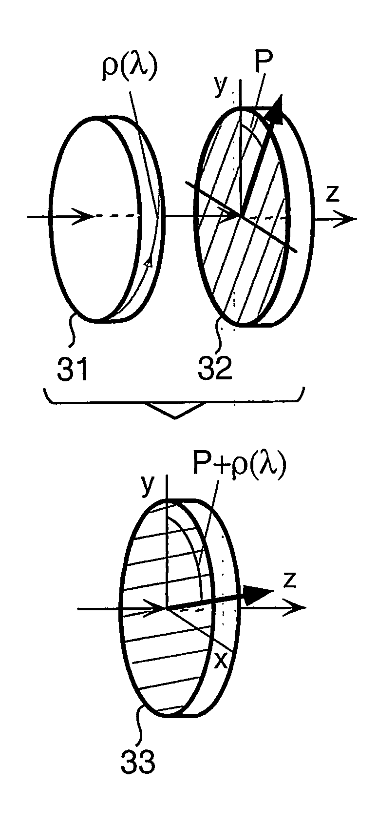
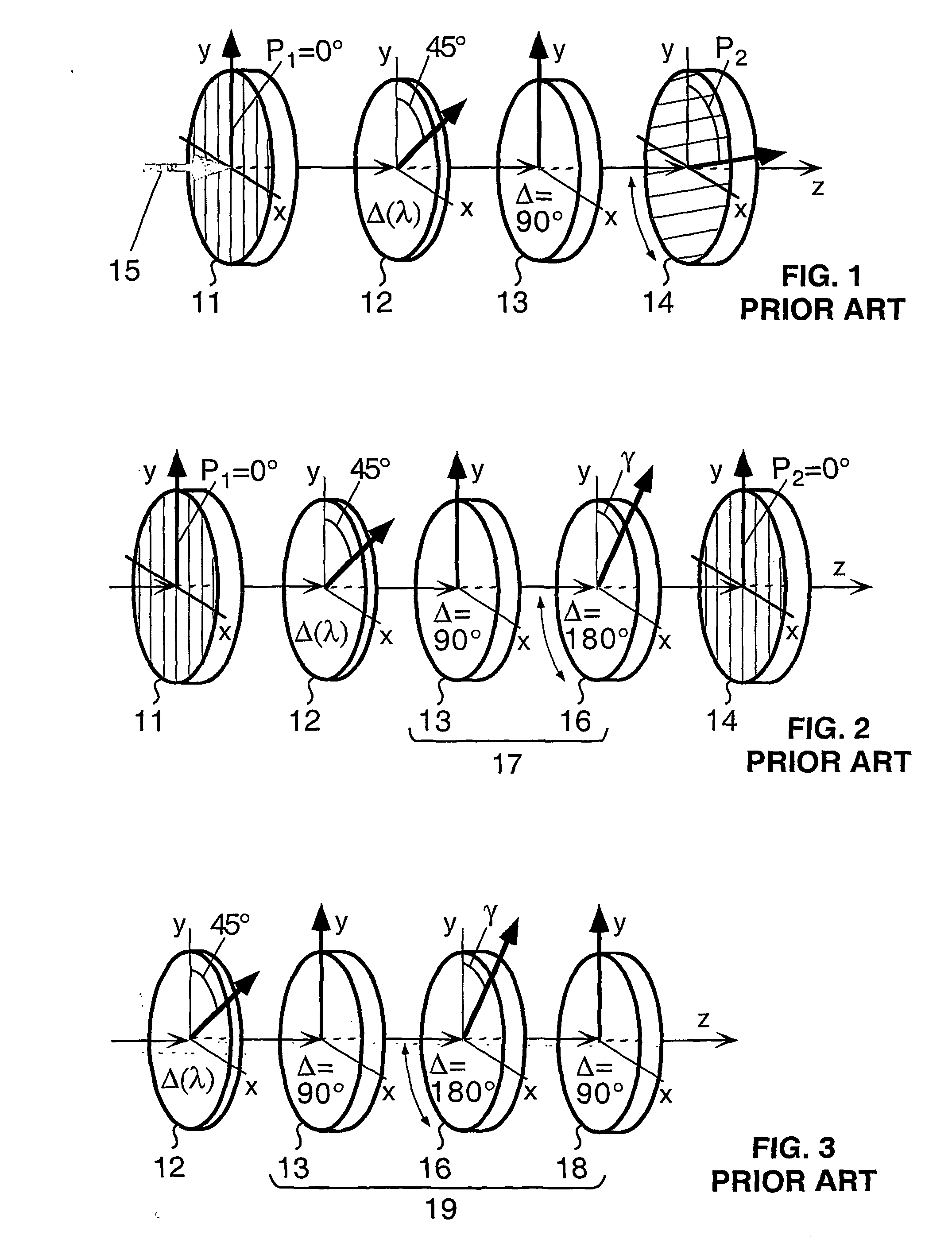
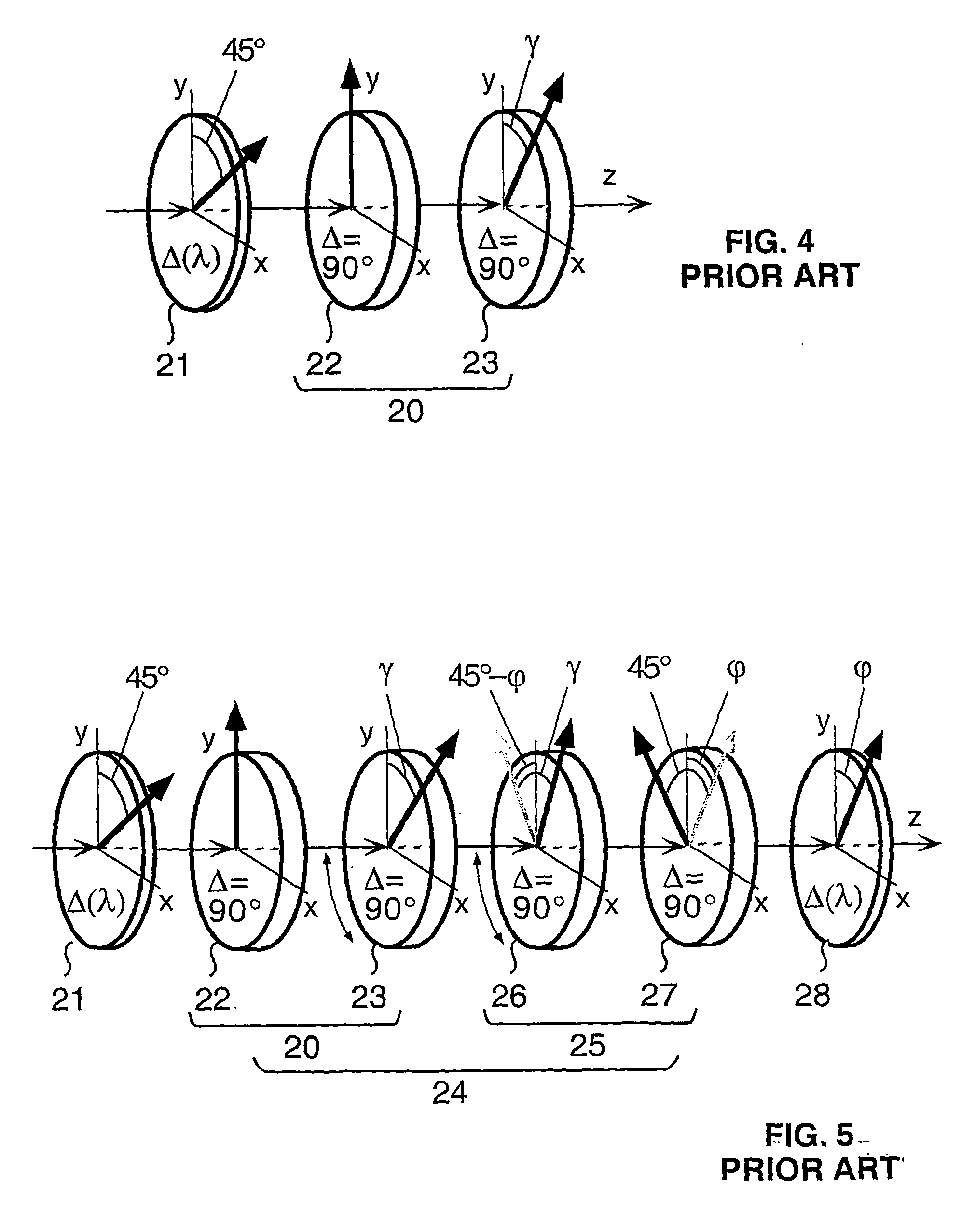
[0057] The elements of the filters or optical systems of this invention are optically connected in cascade. In the drawings, the same number appearing in one drawing refers to the same element. The same number appearing in more than one drawing refers to elements of the same feature, which can replace each other. The term “polarization rotator” is defined in this description as a component or device serving for rotating polarized light. Thus a polarization rotator may be an optical rotator or a Faraday rotator or some others, e.g. a liquid crystal polarization rotator. The term “retarder” is any element or device capable of changing the phase of an optical beam. The phase shift or retardation (Δ) introduced by a retarder may be wavelength-dependent (Δ(λ)), for example as described by Equation (2), or achromatic over a wavelength range. In addition to polarization rotators, the filters of the invention utilize retarders, preferably selected from birefringent achromatic or zero-order ...


PUM


Abstract

The tuner is a constituent component for constructing a tunable or switchable spectral filter, including single and multiple stage filters and filters without intermediate polarizer, over a wavelength range. It has elements arranged in cascade along a light beam axis including a dispersive polarization rotator that has its rotation angle ρ(λ) varying as a function of light wavelength λ over the wavelength range, an orientation-sensitive polarizing element and means for rotating the polarizing element or/and varying the rotation angle ρ(λ). The polarization rotator and the polarizing element are arranged in series in the spectral filter along the light beam axis with the polarizing element oriented at a predetermined orientation angle related to the structure of the spectral filter. The tuner is operated by rotating the polarizing element to change its orientation in the filter or/and by changing the rotation angle ρ(λ).

Description

FIELD OF THE INVENTION [0001] This invention generally relates to wavelength-tunable optical polarization interference filters, more particularly, to a new concept for constructing tunable spectral filters and new spectral filters developed based on this concept. BACKGROUND OF THE INVENTION [0002] Polarization is the phenomenon, which is exhibited when a transverse wave is polarized. Light is a transverse electromagnetic wave that vibrates in a direction perpendicular to the direction of propagation. Ordinary light is unpolarized, consisting of a mixture of waves vibrating in all directions. In an unpolarized wave, the vibrations in a plane perpendicular to the ray appear to be oriented in all directions with equal probability. Light is said to be polarized if the direction of the vibrations is completely predicable and remains constant for some reason. [0003] There are different ways for producing linearly polarized light, for example by using so called polarizers. A polarizer is a...

Claims


Application Information

Patent Timeline
IPC IPC(8): G02B27/00G02B27/28G02F1/09G02F1/1347G02F1/139G02F1/141
CPCG02B27/286G02B27/288G02F1/09G02F2203/055G02F1/1396G02F1/141G02F2202/40G02F1/13473
Inventor YE, CHUN
Owner YE CHUN
Why Eureka
Try Eureka