Zoom lens and projection display device using the zoom lens

a technology of zoom lens and projection display device, which is applied in the field of zoom lens, can solve the problems of insufficient satisfaction of the requirements of the overall length of the lens system, and insufficient satisfaction of the requirements of the recent years of shortening the lens system. achieve the effect of short overall length, favorable aberration correction, and bright imag

Inactive Publication Date: 2006-03-16
FUJI PHOTO OPTICAL CO LTD
View PDF4 Cites 19 Cited by
  • Summary
  • Abstract
  • Description
  • Claims
  • Application Information

AI Technical Summary

Benefits of technology

[0012] The present invention relates to a zoom lens having a short overall length that can be constructed with only five lens groups, only three of which move during zooming, that can provide favorable correction of aberr

Problems solved by technology

However, the overall length of the lens system fails to sufficiently satisfy the requirements of recent years of shortening the lens system.
In addition, when an f-number of 1.7 at the wide-angle end is provided, the requirements of recent years of shortening the lens system are not adequately satisfied.
In addition, when an f-number of 1.84 is provided, the requirements of recent years of shortening the lens system are not adequately

Method used


Image

  • Zoom lens and projection display device using the zoom lens
  • Zoom lens and projection display device using the zoom lens
  • Zoom lens and projection display device using the zoom lens

Examples


embodiment 1

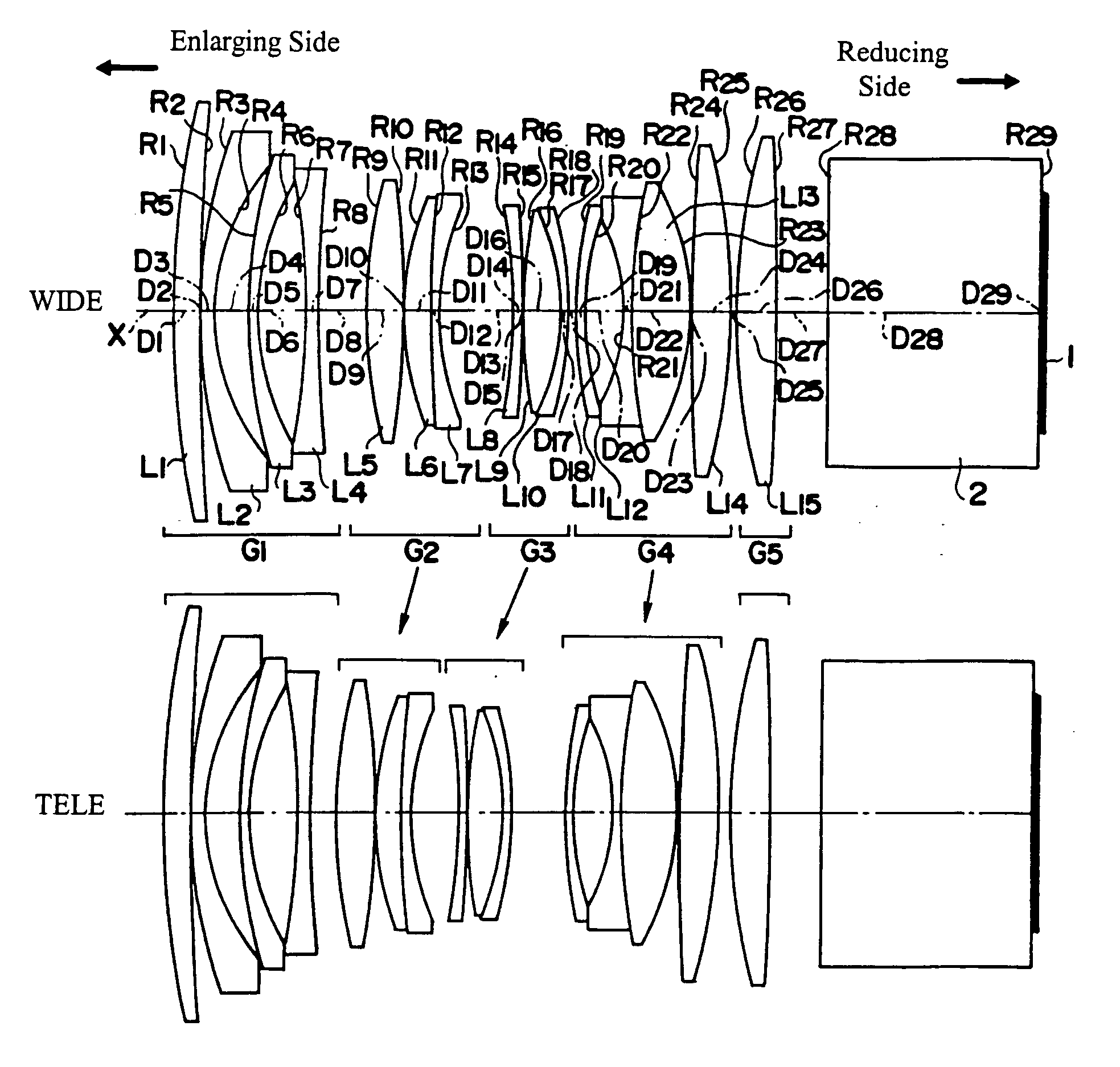
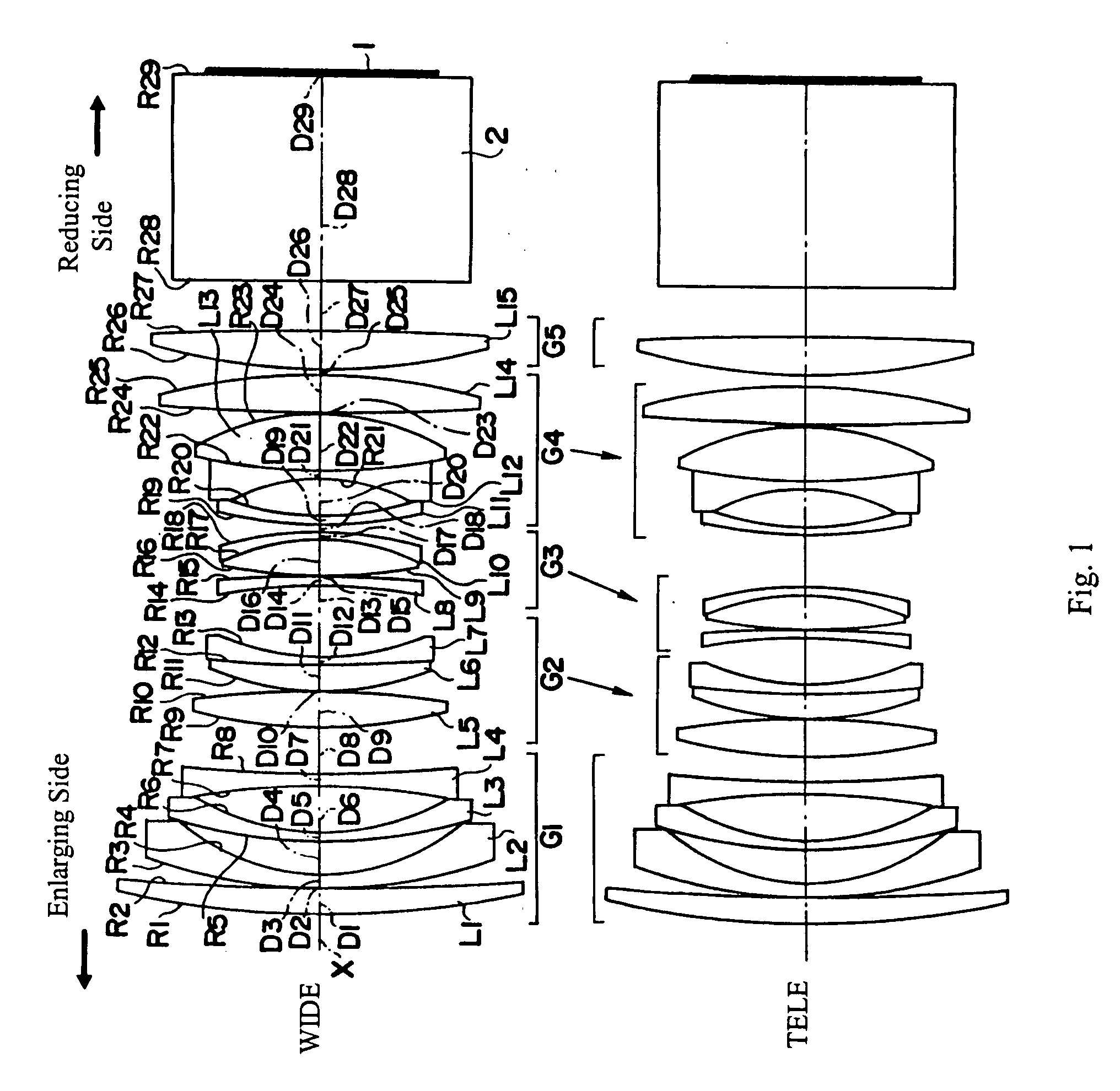
[0045]FIG. 1 shows cross-sectional views of Embodiment 1 of the present invention at the wide-angle end (WIDE) and at the telephoto end (TELE), as discussed above. As shown in FIG. 1, the first lens group G1 includes, in order from the enlarging side: a first lens element L1 having positive refractive power and a meniscus shape with its convex surface on the enlarging side; a second lens element L2 having negative refractive power and a meniscus shape with its convex surface on the enlarging side; a third lens element L3 having negative refractive power and a meniscus shape with its convex surface on the enlarging side; and a fourth lens element L4 having a biconcave shape formed of surfaces with different radii of curvature, with the surface of stronger curvature on the enlarging side. The second lens group G2 includes, in order from the enlarging side: a fifth lens element L5 having a biconvex shape formed of surfaces with different radii of curvature, with the surface of stronger...

embodiment 2

[0052] Embodiment 2 is very similar to Embodiment 1 and uses the same number of lens elements. Because Embodiment 2 is very similar to Embodiment 1, only the differences between Embodiment 2 and Embodiment 1 will be explained for Embodiment 2. Embodiment 2 differs from Embodiment 1 in its lens element configuration by having different radii of curvature of the lens surfaces, different optical element surface spacings, and some different refractive indexes and Abbe numbers.

[0053] Table 4 below lists the surface number #, in order from the enlarging side, the radius of curvature R of each surface, the on-axis surface spacing D, as well as the refractive index Nd and the Abbe number vd (at the d-line of 587.6 nm) of each optical element for Embodiment 2, except that the on-axis surface spacings that vary with zooming are listed in Table 5 below. The numerical values of R and D are based on a normalized focal length of 1.00 at the wide-angle end configuration of the zoom lens of Embodi...

embodiment 3

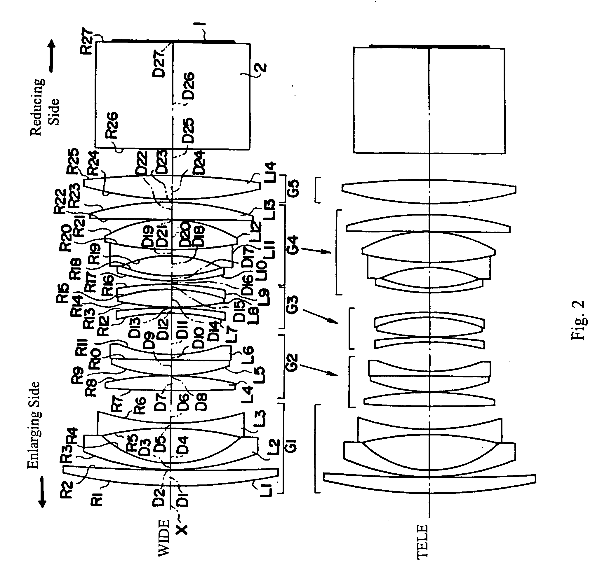
[0058]FIG. 2 shows cross-sectional views of Embodiment 3 of the present invention at the wide-angle end (WIDE) and at the telephoto end (TELE). Embodiment 3 is very similar to Embodiment 1. Because Embodiment 3 is very similar to Embodiment 1, only the differences between Embodiment 3 and Embodiment 1 will be explained for Embodiment 3.

[0059] A primary difference between Embodiments 1 and 2 versus Embodiment 3 is that in Embodiment 3 the first lens group G1 includes only three lens elements that are lens components rather than four lens elements that are lens components. In particular, in Embodiment 3, the first lens group G1 includes, in order from the enlarging side: a first lens element L1 having positive refractive power and a meniscus shape with its convex surface on the enlarging side; a second lens element L2 having negative refractive power and a meniscus shape with its convex surface on the enlarging side; and a third lens element L3 that is biconcave having surfaces of di...


PUM


Abstract

A zoom lens for a projection display device includes, in order from the enlarging side, a first lens group having negative refractive power and that is stationary during zooming, second and third lens groups having positive refractive power, a fourth lens group that has refractive power that is much weaker in absolute value than the refractive powers of the other lens groups, and a fifth lens group having positive refractive power and that is stationary during zooming. The second, third, and fourth lens groups move with coordinated movements continuously toward the enlarging side during zooming from the wide-angle end to the telephoto end of the zoom range. The zoom lens satisfies certain conditions related to focal lengths of the zoom lens and lens groups and distances along the optical axis. A projection display device uses the zoom lens.

Description

TECHNICAL FIELD OF THE INVENTION [0001] The present invention relates to a zoom lens for projecting images, such as in projection television systems, and relates in particular to liquid crystal projection display devices and to projection display devices that use the zoom lens of the present invention. BACKGROUND OF THE INVENTION [0002] Generally, in zoom lenses used as projection lenses in projection display devices, an aperture diameter corresponding to a liquid crystal projector for providing a bright projected image is desired. Compactness of the zoom lens in order to make the projection-type display device small is also desired. In addition, these zoom lenses need to define optical systems that are telecentric, or nearly telecentric, on the reducing side where the display element, such as a liquid crystal display element, is positioned, and that have appropriately large back focal lengths so that there is sufficient room for a color synthesizing optical system (which would oper...

Claims


Application Information

Patent Timeline
IPC IPC(8): G02B15/14
CPCG02B15/177G02B13/22G02B15/145531
Inventor NAKAZAWA, KIMIAKIWATANABE, FUMIO
Owner FUJI PHOTO OPTICAL CO LTD
Why Eureka
Try Eureka