
Electromagnetic interference filter for an autotransformer

a technology of electromagnetic interference and autotransformer, which is applied in the direction of reducing harmonics/ripples, electrical equipment, power conversion systems, etc., can solve the problems of emi transmission back into, emi radiation and conducted electromagnetic interference (emi) for aircraft systems, etc., and achieve the effect of reducing the size, weight and cost of the differential mode emi filter

Active Publication Date: 2006-03-16
HONEYWELL INT INC
View PDF19 Cites 32 Cited by
  • Summary
  • Abstract
  • Description
  • Claims
  • Application Information

AI Technical Summary

Benefits of technology

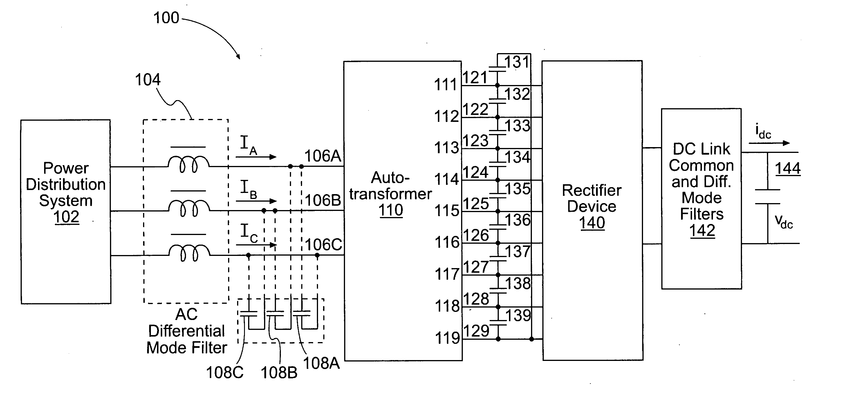
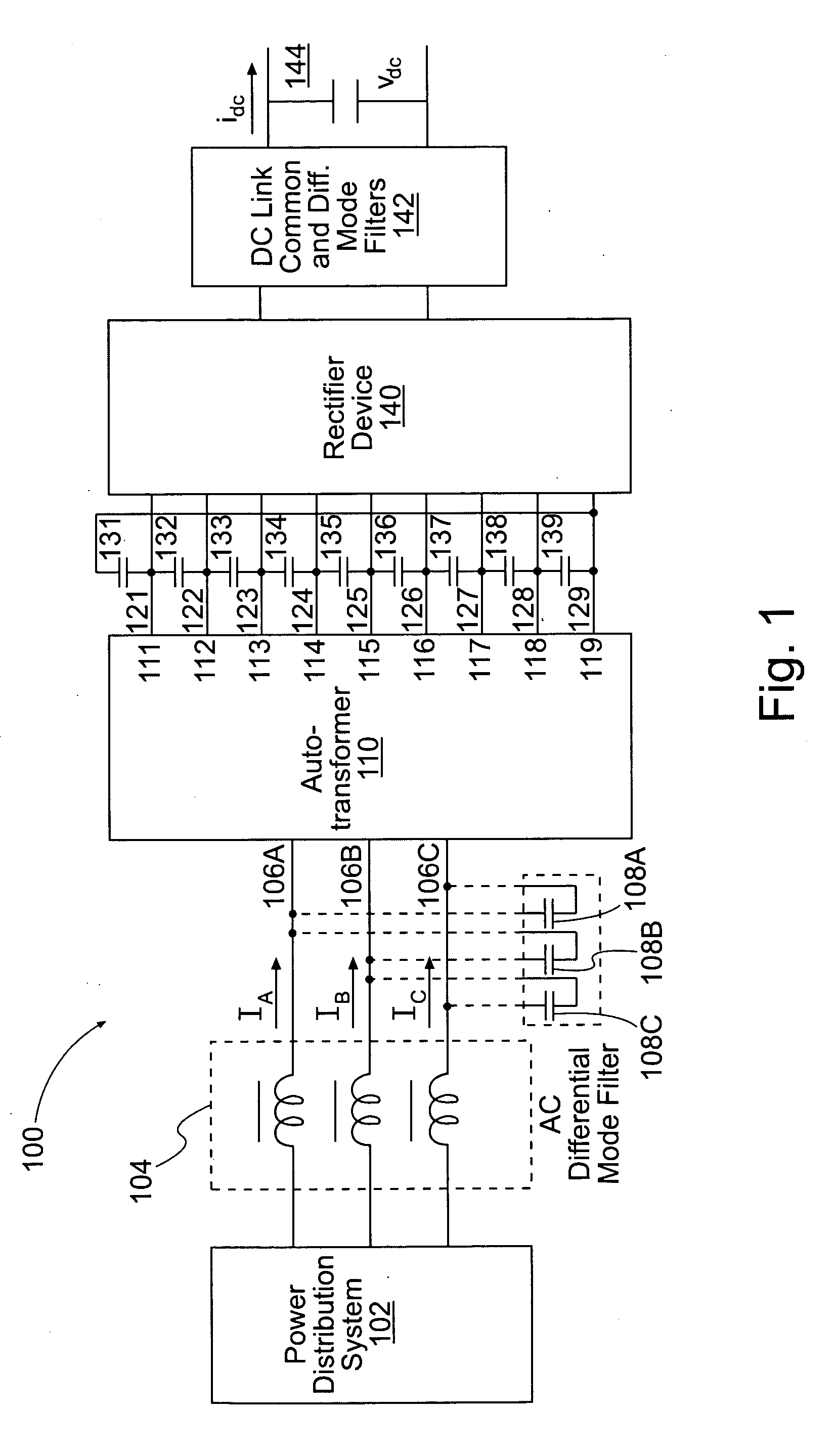
[0005] The invention relates to systems and methods for an EMI filter. The invention utilizes the leakage inductance of the autotransformer and one or more capacitors on the secondary side and optionally one or more differential mode inductors and capacitors on the primary side to form a differential mode EMI filter. This configuration reduces the size, weight, and cost of the differential mode EMI filter when compared with a differential filter formed by placing the inductors and capacitors on the primary side only. In one embodiment, the invention is an EMI filter system to be used with a rectification system for attenuating electromagnetic interference. The EMI filter system includes an autotransformer having first, second and third input nodes and first, second and third output nodes. The EMI filter system also includes a first output capacitor coupled to the first and second output nodes and a second output capacitor coupled to the second and third output nodes.

Problems solved by technology

Emissions from these AC power systems may produce radiated and conducted electromagnetic interference (EMI) for aircraft systems.
For example, the emissions may transmit EMI distortion back into the AC power systems.

Method used


Image

  • Electromagnetic interference filter for an autotransformer
  • Electromagnetic interference filter for an autotransformer
  • Electromagnetic interference filter for an autotransformer

Examples


Embodiment Construction

[0020] Systems and methods that implement the embodiments of the various features of the invention will now be described with reference to the drawings. The drawings and the associated descriptions are provided to illustrate embodiments of the invention and not to limit the scope of the invention. Reference in the specification to “one embodiment” or “an embodiment” is intended to indicate that a particular feature, structure, or characteristic described in connection with the embodiment is included in at least an embodiment of the invention. The appearances of the phrase “in one embodiment” in various places in the specification are not necessarily all referring to the same embodiment. Throughout the drawings, reference numbers are re-used to indicate correspondence between referenced elements. In addition, the first digit of each reference number indicates the figure in which the element first appears.

[0021] Referring now more particularly to the drawings, FIG. 1 is a block diagr...


PUM


Abstract

A filter system for attenuating electromagnetic interference (EMI) of an autotransformer-based rectification system that utilizes the leakage inductance of the autotransformer and one or more capacitors connected on the secondary side and optionally one or more differential mode inductors and input capacitors connected on the primary side to form a differential mode EMI filter. This configuration reduces the size, weight, and cost of the differential mode EMI filter when compared with a differential filter formed by placing the inductors and capacitors on the primary side.

Description

FIELD OF THE INVENTION [0001] The invention relates generally to an electromagnetic interference filter for aircraft power systems, and more particularly to an electromagnetic interference filter to be used with multi-pulse rectification systems for achieving power quality. BACKGROUND [0002] Various passive and active solutions have been developed to achieve a specified power quality for aircraft systems. Some passive solutions include passive filters, multi-pulse transformers, and multi-pulse autotransformers. Some active solutions include active rectifiers, active filters, and matrix converters. Multi-pulse autotransformers are generally more desirable than multi-pulse transformers in aircraft applications because of their smaller size, weight and costs. Multi-pulse autotransformers can be configured as 12-pulse, 18-pulse, 24-pulse, and 30-pulse rectification systems, and even more for aircraft applications. When 6-pulse rectifiers are paralleled, interphase transformers are norma...

Claims


Application Information

Patent Timeline
IPC IPC(8): H02M1/12
CPCH02M1/126H02M7/08H02M1/44
Inventor SARLIOGLU, BULENT
Owner HONEYWELL INT INC
Learn More