Mechanism to improve preemption behavior of resource reservations

a resource reservation and preemption behavior technology, applied in the field of network communication, can solve the problems of all other fate-sharing flows in the group consequently losing their utility, and achieve the effects of avoiding resource reservations, avoiding resource reservation disruptions, and avoiding resource reservations efficiently

Active Publication Date: 2006-03-16
CISCO TECH INC
View PDF14 Cites 62 Cited by
  • Summary
  • Abstract
  • Description
  • Claims
  • Application Information

AI Technical Summary

Benefits of technology

[0027] Advantageously, the inventive technique may be used to preempt data flows efficiently in both client nodes and / or intermediate network nodes with minimal disruptions of existing application instances. Further, the data flows in the present invention may originate from and / or terminate on the same or different network nodes in a network. The inventive technique may be used to preempt resource reservations efficiently in accordance with a resource reservation protocol, such as the Resource ReSerVation Protocol (RSVP).

Problems solved by technology

In other words, if any of the fate-shared data flows is preempted and thus terminated (“torn down”), all other fate-sharing flows in the group consequently lose their utility.

Method used


Image

  • Mechanism to improve preemption behavior of resource reservations
  • Mechanism to improve preemption behavior of resource reservations
  • Mechanism to improve preemption behavior of resource reservations

Examples


Embodiment Construction

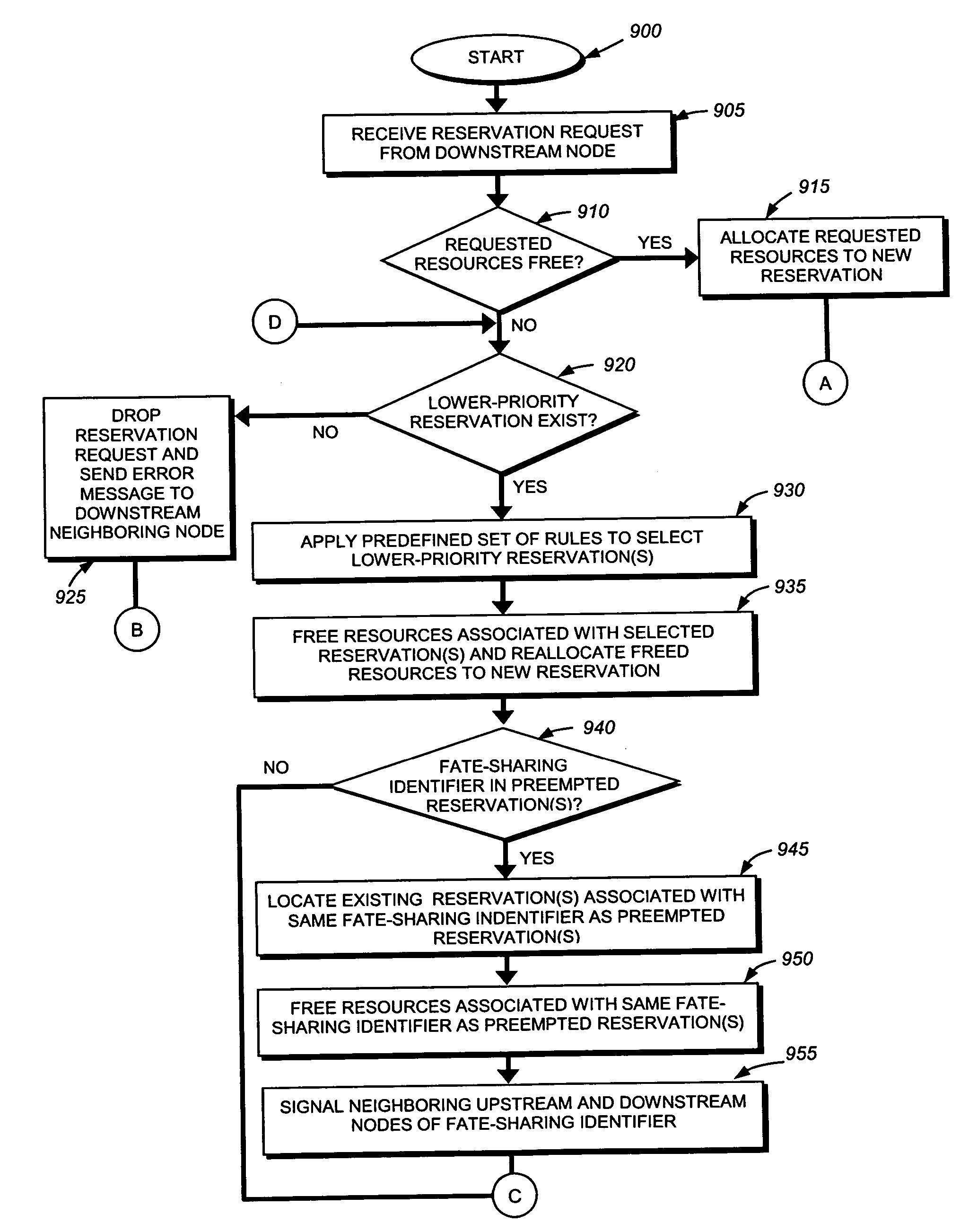
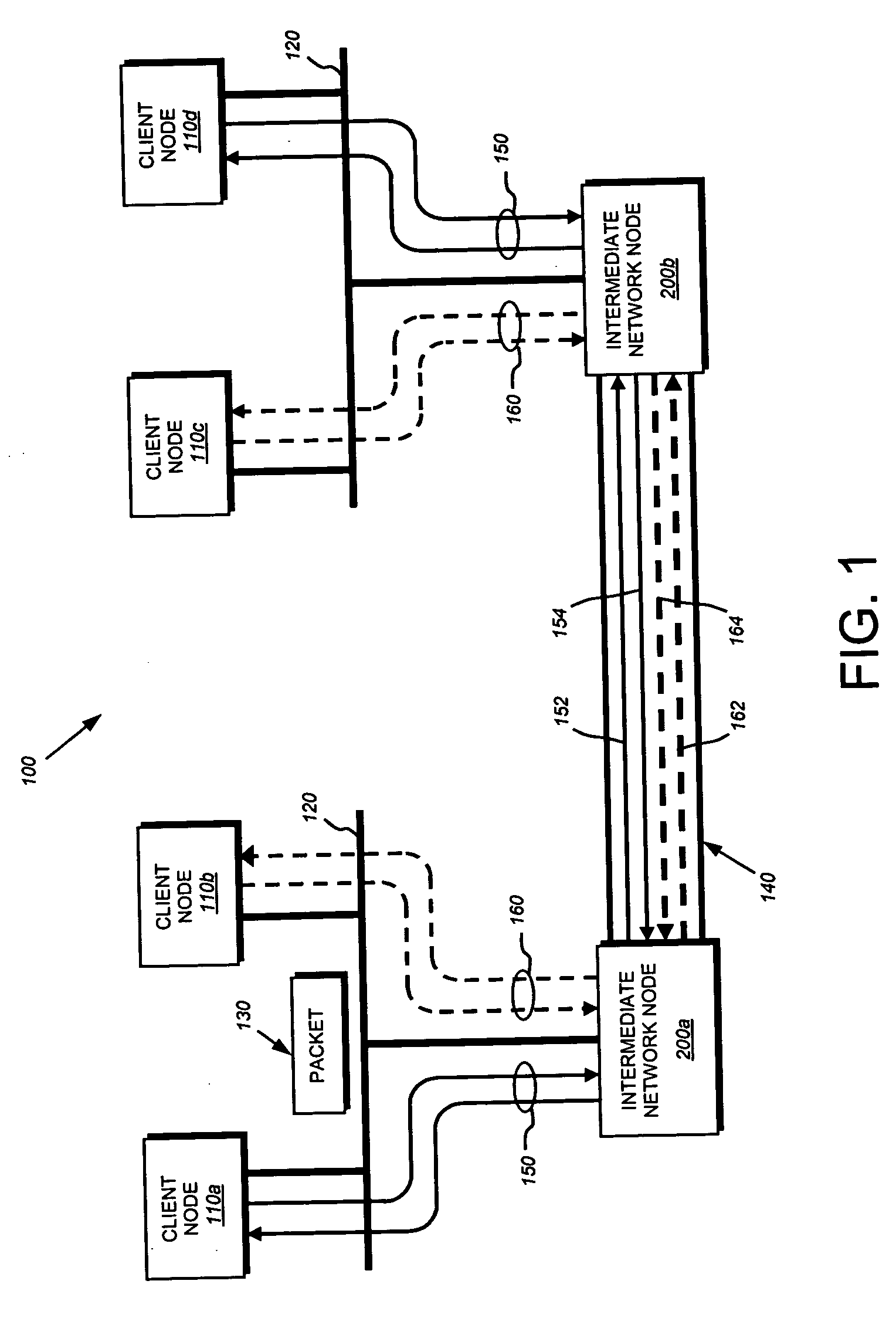
[0041]FIG. 1 is a schematic block diagram of a network 100 that advantageously may be used with the present invention. The network comprises a plurality of interconnected network nodes, such as client nodes 110 and intermediate network nodes 200. The nodes may be coupled to one another over local area networks (LAN) 120, point-to-point links 140, wide area networks (WAN), wireless LANs, etc. to form the network 100. The interconnected network nodes may exchange discreet data packets 130 which are formatted according to predefined sets of network communication protocols, such as the Transmission Control Protocol / Internet Protocol (TCP / IP) and the Resource Reservation Protocol (RSVP).

[0042] A unidirectional stream of data packets 130, or a “data flow,” may be transmitted from a source client node to a destination client node. The data flow may traverse one or more intermediate network nodes 200, such as routers or switches, positioned along the data path interconnecting the source an...


PUM


Abstract

A technique is provided for one or more network nodes to deterministically select data flows to preempt. In particular, each node employs a set of predefined rules which instructs the node as to which existing data flow should be preempted in order to admit a new high-priority data flow. The rules are precisely defined and are common to all nodes configured in accordance with the present invention. Illustratively, a network node not only selects a data flow to preempt, but additionally may identify other “fate sharing” data flows that may be preempted. As used herein, a group of data flows has a fate-sharing relationship if the application instance(s) containing the data flows functions adequately only when all the fate-shared flows are operational. In a first illustrative embodiment, after a data flow in a fate-sharing group is preempted, network nodes may safely tear down the group's remaining data flows. In a second illustrative embodiment, when a data flow is preempted, all its fate-shared data flows are marked as being “at risk.” Because the at-risk flows are not immediately torn down, it is less likely that resources allocated for the at-risk flows may be freed then subsequently used to establish relatively lower-priority data flows instead of relatively higher-priority data flows.

Description

FIELD OF THE INVENTION [0001] This invention relates generally to network communications, and, more specifically, to a technique that enables network nodes to efficiently preempt relatively lower-priority data flows in favor of relatively higher-priority data flows. BACKGROUND INFORMATION [0002] A computer network is a geographically distributed collection of interconnected subnetworks for transporting data between network nodes, such as computers. A local area network (LAN) is an example of such a subnetwork. The network's topology is defined by an arrangement of client nodes that communicate with one another, typically through one or more intermediate network nodes, such as routers or switches. As used herein, a client node is a network node that is configured to originate or terminate communications over the network. In contrast, an intermediate network node is a node that facilitates routing data between client nodes. Communications between network nodes are typically effected b...

Claims


Application Information

Patent Timeline
Patent Type & Authority Applications(United States)
IPC IPC(8): H04L12/26
CPCH04L43/00H04L12/26
Inventor BAKER, FREDERICKDAVIE, BRUCE S.ORAN, DAVID R.ITURRALDE, CAROLLEVESQUE, ROGERDIBIASIO, MICHAEL V.
Owner CISCO TECH INC
Why Eureka
Try Eureka