Arrangement for two-dimensional or three-dimensional representation

Inactive Publication Date: 2006-03-16
VIA ONE VISION HLDG S A R L
View PDF8 Cites 44 Cited by
  • Summary
  • Abstract
  • Description
  • Claims
  • Application Information

AI Technical Summary

Benefits of technology

[0049] The problem is also solved according to the invention by an arrangement as described by the generic part of claim 2, in which, as a means for uniform illumination in the second mode of operation, a switchable scattering disk is arranged between the light guide and the image display device, which is switched to be transparent in the first mode of operation and to be scattering in at least part of its surface area in the second mode of operation, so as to reduce the brightness contrast of the light passing the switchable scattering disk in the second mode of operation. The contrast reduction contributes to homogenizing the illumination in the second mode of operation, i.e., in the mode for two-dimensional display.
[0050] In the last-named embodiment of the invention, too, the first light source may be switched on in addition to the second one in the second mode of operation. Unlike the embodiment described first, however, the brightness of the first light source (which emits light towards the observer through the transparent filter elements and further components of the arrangement) may be much higher than the brightness of the second light source (the light of which is emitted towards the observer especially on the opaque filter elements). As a result, a yet higher brightness is achieved in the second mode of operation.
[0051] The embodiment of the invention described last has the added advantage of particular

Problems solved by technology

The disadvantage is that this is a two-channel 3D display for a single observer, who needs to occupy a fixed viewing position.
In addition, at viewing positions other than that at the correct depth in front of the 3D display, heavy, interfering moire effects are visible.
By the way, manufacturing the device calls for considerable process expend

Method used


Image

  • Arrangement for two-dimensional or three-dimensional representation
  • Arrangement for two-dimensional or three-dimensional representation
  • Arrangement for two-dimensional or three-dimensional representation

Examples


first embodiment

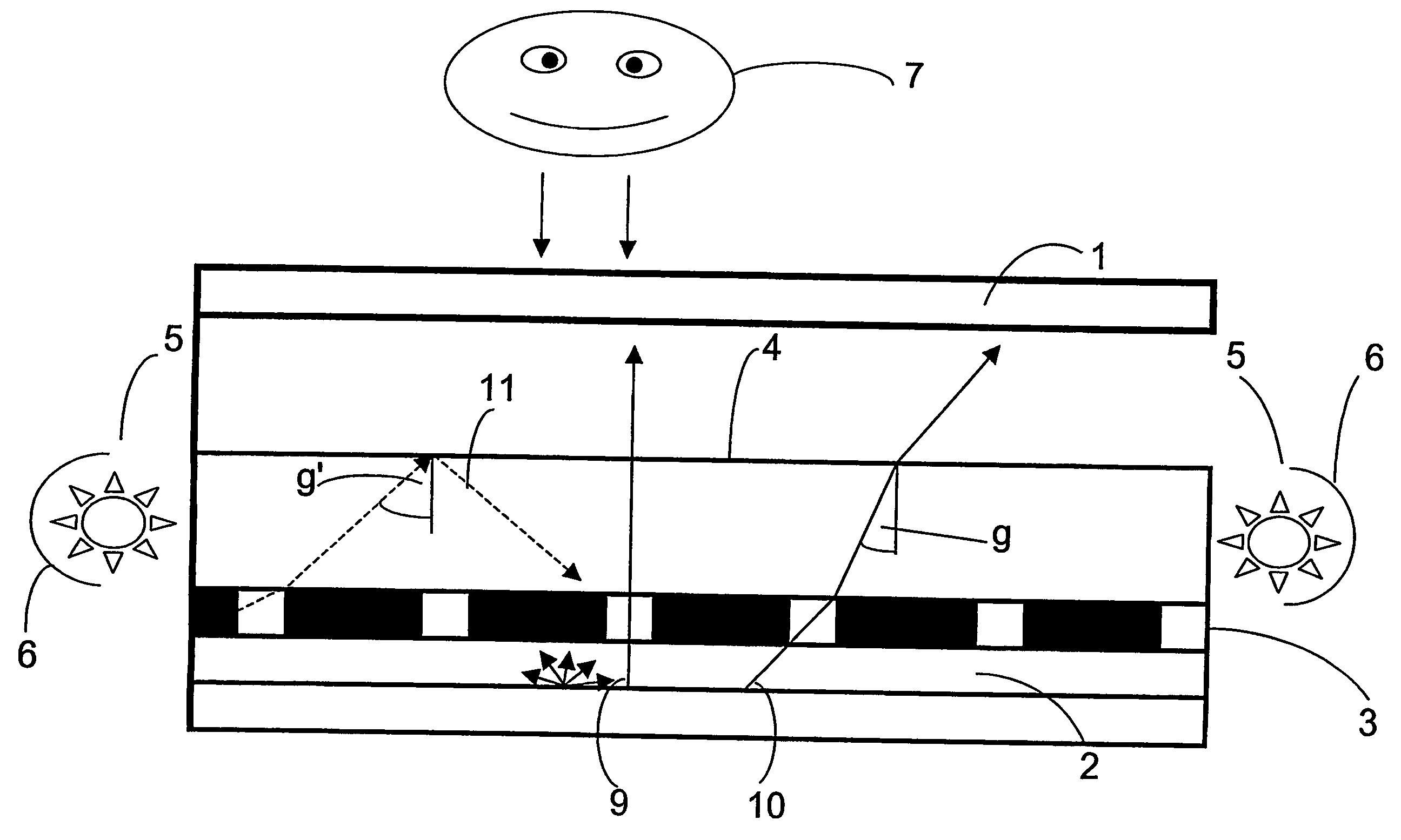
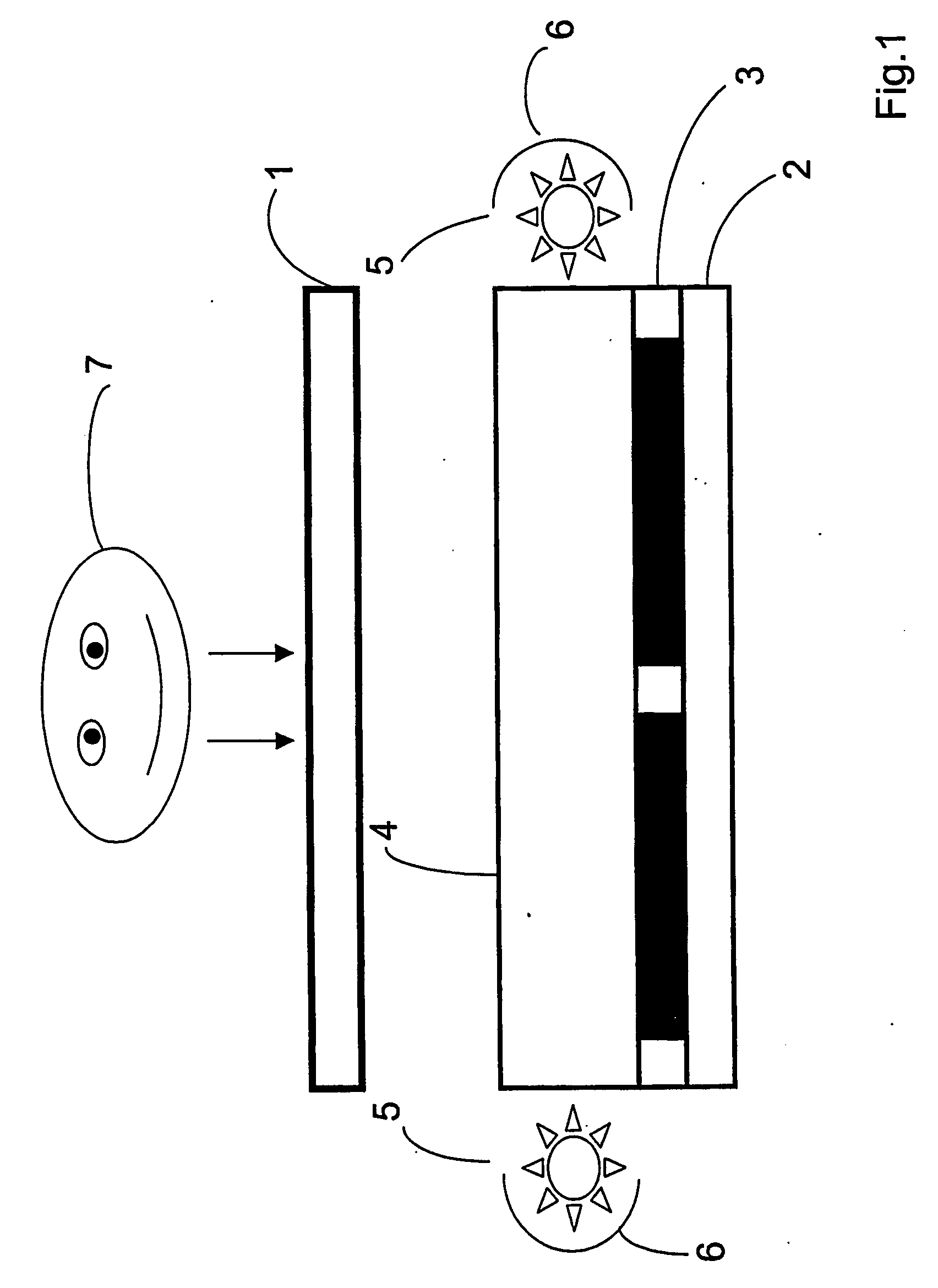
[0070]FIG. 1 shows the general principle of arrangements according to the invention,

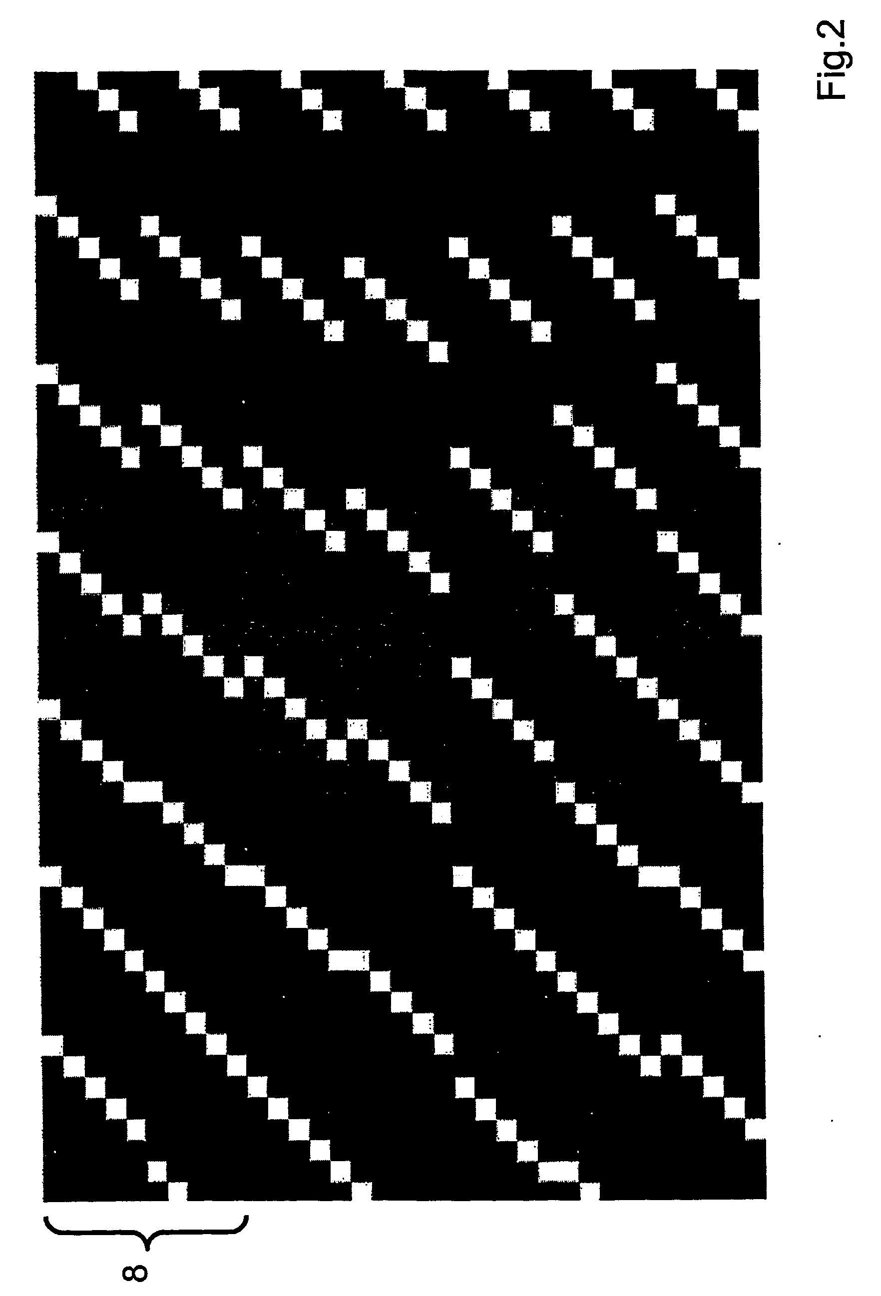
[0071]FIG. 2 shows an example of a wavelength filter array for use in the first embodiment of arrangements according to the invention (detail),

[0072]FIG. 3 shows an image combination rule for displaying image information from several (here: nine) views on the image display device (detail),

[0073]FIG. 4 shows an example of a monocular vision, based on the conditions prevailing in FIG. 2 and FIG. 3,

[0074]FIG. 5 shows another example of a wavelength filter array for use in the first embodiment of arrangements according to the invention (detail),

[0075]FIG. 6 shows another image combination rule for displaying image information from several (here: eight) views on the image display device (detail),

[0076]FIG. 7 shows an example of a monocular vision, based on the conditions prevailing in FIG. 5 and FIG. 6,

[0077]FIG. 8 is a schematic presentation of the joint action of the first and second light sources...


PUM


Abstract

An arrangement for two- or three-dimensional display including an image display device consisting of a multitude of light-transmitting image rendering elements, on which bits of image information from several perspective views can be displayed, and a wavelength filter array and a controllable illuminator providing at least two modes of operations. In a first mode of operation, light emitted by a first light source arranged behind the wavelength filter array reaches the observer by passing through at least part of the light-transmitting filter elements and subsequently through a correlated part of the image rendering elements of the image display device, so that the scene or object is seen by the observer in three dimensions. In a second mode of operation, light emitted by a second light source reaches the observer by passing through the image rendering elements of the image display device but not through the filter elements of the wavelength filter array, so that the scene or object is seen by the observer at least partially in two dimensions, with uniform illumination in the second mode of operation being provided by suitable means.

Description

FIELD OF THE INVENTION [0001] The invention relates to an arrangement for two- or three-dimensional display. DESCRIPTION OF THE PRIOR ART [0002] Many autostereoscopic display methods are based on the principle of the simultaneous optical rendering of several views of an object or scene with different perspectives, while using suitable means to make different selections of these perspective views visible to an observer's right and left eyes separately. This creates an effect of parallax, which allows the observer a spatial perception with distinct depth discrimination. [0003] In the course of research in the field of autostereoscopic display, many methods and arrangements have been developed that give spatial impressions to one or several observers with unaided eyes. These arrangements often allow but a limited rendering of plain text or two-dimensional graphs; this is the case, for example, with U.S. Pat. No. 5,457,574 and U.S. Pat. No. 5,606,455. For users, however, it is of great ...

Claims


Application Information

Patent Timeline
IPC IPC(8): G02B6/10H04N13/00
CPCH04N13/0454H04N13/0418H04N13/32H04N13/359
Inventor TZSCHOPPE, WOLFGANG
Owner VIA ONE VISION HLDG S A R L
Why Eureka
Try Eureka