Apparatus and methods for cooling turbine bucket platforms

a bucket platform and cooling turbine technology, applied in the direction of blade accessories, machine/engine, engine fuction, etc., can solve the problems of increasing the distress of bucket platforms, oxidation, creep cracking, low cycle fatigue cracking, etc., to improve the output and engine efficiencies, increase the inlet firing temperature, and exacerbate the potential distress

Inactive Publication Date: 2006-03-16
GENERAL ELECTRIC CO
View PDF7 Cites 39 Cited by
  • Summary
  • Abstract
  • Description
  • Claims
  • Application Information

AI Technical Summary

Benefits of technology

[0002] Over the years, gas turbines have trended towards increased inlet firing temperatures to improve output and engine efficiencies. As gas path temperatures have increased, bucket platforms have increasingly exhibited distress including oxidation, creep and low cycle fatigue cracking. In certain turbines, temperature inlet profiles have become such that the platforms are seeing close to the peak inlet temperatures for the blade row. This exacerbates the potential distress on bucket platforms as these blades run even hotter.
[0003] Many prior bucket designs did not require active cooling of the platform due to low firing temperatures. Also, film cooling carryover from upstream nozzle side walls tended to lower the temperatures near the platforms from the resulting “pitch-line bias” of the inlet temperature profile. Newer bucket designs have utilized film cooling by drilling holes through the platform and using compressor discharge air to flow a layer of film air on the platform surface exposed to the hot gas path, protecting it from the high flow path temperatures. This, however, is limited to areas where there is sufficient pressure to inject the air to film cool surface portions of the platform exposed to the hot gas flow path. Many current bucket designs only have sufficient pressure to film cool the aft section of the platform where the gas flow path air has been accelerated to drop the local static pressure. Accordingly, there is the need to reduce the platform temperature to a level required to meet part life or durability requirements including oxidation, creep and low cycle fatigue cracking.

Problems solved by technology

As gas path temperatures have increased, bucket platforms have increasingly exhibited distress including oxidation, creep and low cycle fatigue cracking.
This exacerbates the potential distress on bucket platforms as these blades run even hotter.
Also, film cooling carryover from upstream nozzle side walls tended to lower the temperatures near the platforms from the resulting “pitch-line bias” of the inlet temperature profile.
This, however, is limited to areas where there is sufficient pressure to inject the air to film cool surface portions of the platform exposed to the hot gas flow path.
Many current bucket designs only have sufficient pressure to film cool the aft section of the platform where the gas flow path air has been accelerated to drop the local static pressure.

Method used


Image

  • Apparatus and methods for cooling turbine bucket platforms
  • Apparatus and methods for cooling turbine bucket platforms
  • Apparatus and methods for cooling turbine bucket platforms

Examples


Embodiment Construction

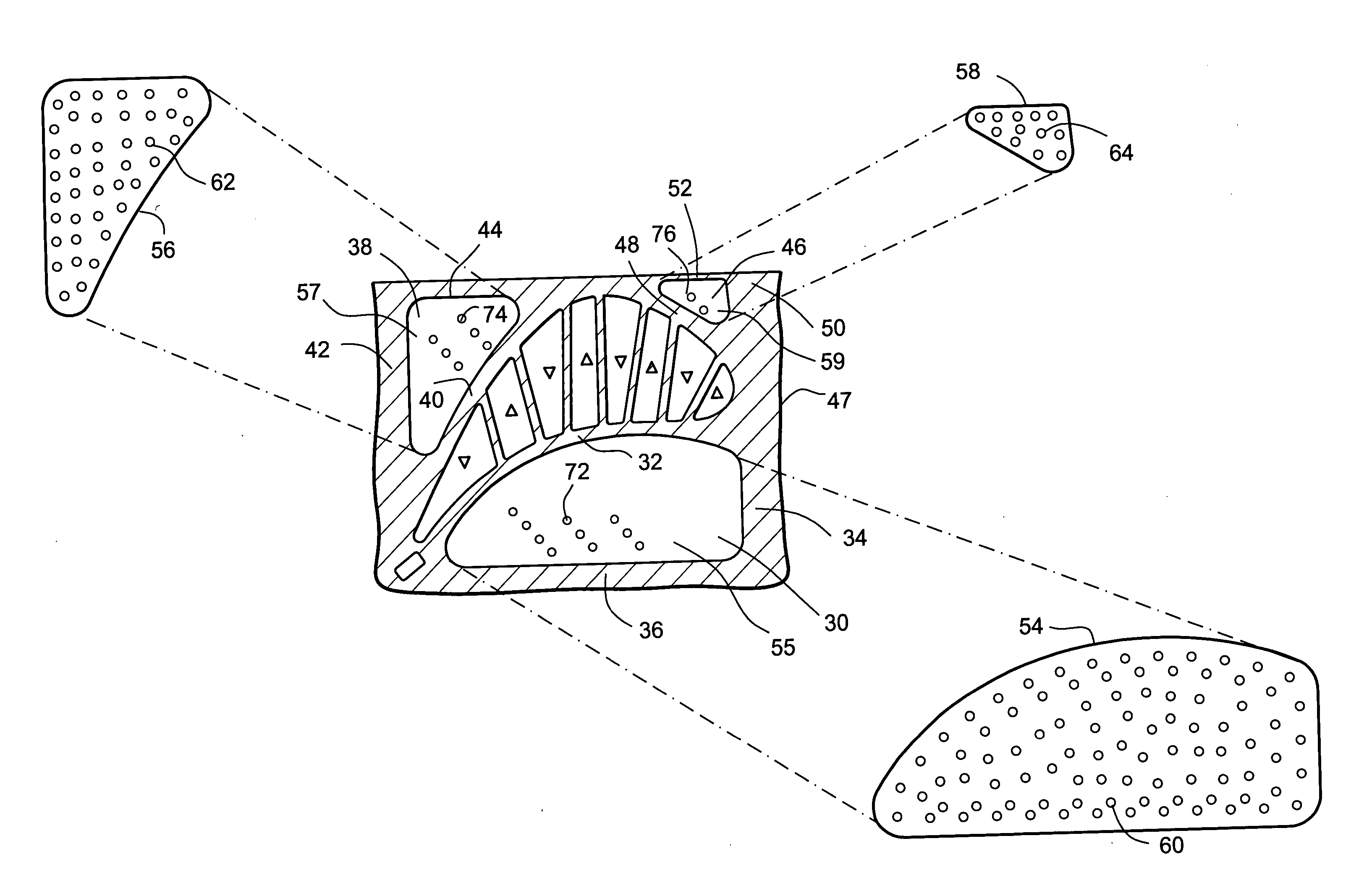
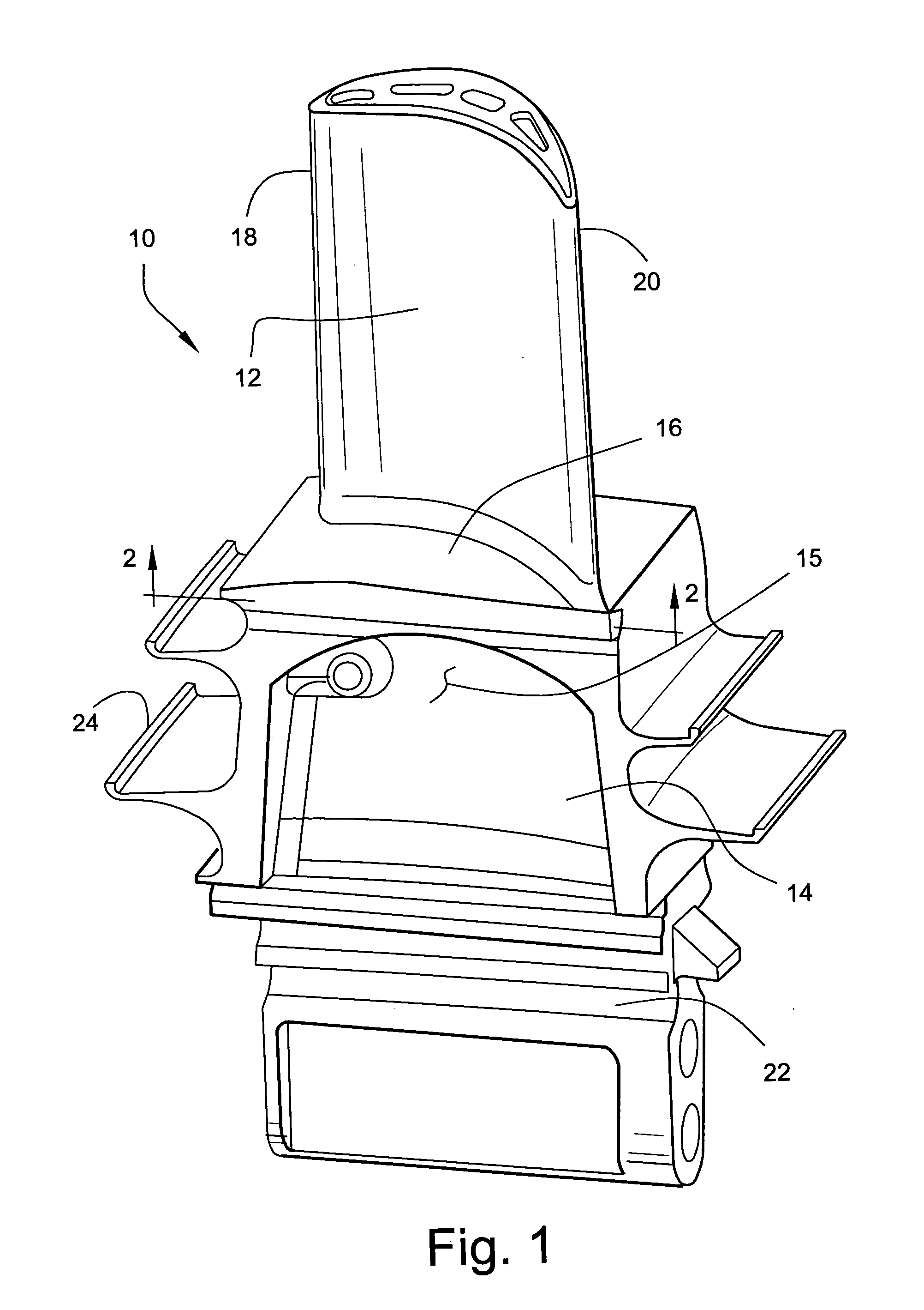
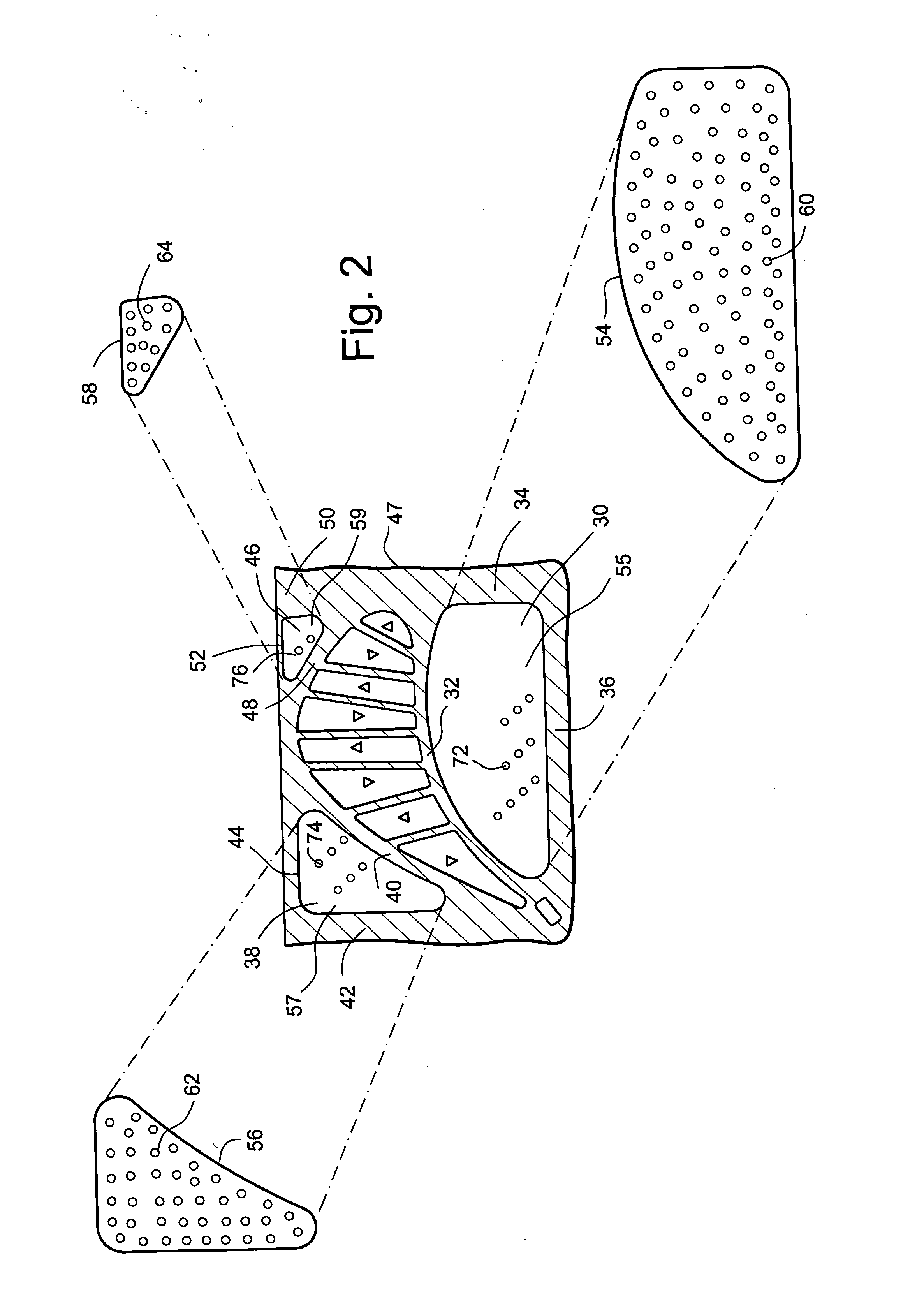
[0009] Referring to the drawings, particularly to FIG. 1, a turbine bucket, generally designated 10 includes an airfoil 12 and a shank 14 with a platform 16 interfaced between the airfoil 12 and shank 14. The airfoil 12, of course, extends radially outwardly from the platform 16 and includes leading and trailing edges 18 and 20, respectively. Below the shank 14 is a dovetail 22 forming part of the base of the bucket. It will be appreciated that the buckets 10 are arranged in a circumferentially spaced array thereof in generally correspondingly shaped dovetail grooves in the rim of a turbine rotor wheel, not shown. So-called angel wing seals 24 are provided on the forward and aft faces of the shank 14 of the bucket 10 for sealing purposes as is conventional. Typically, a cooling medium, e.g., compressor discharge air, is provided in the base of the bucket and circulated along the bucket shank and through the airfoil to cool the airfoil. The cooling medium typically discharges into th...


PUM


Abstract

A turbine bucket includes a platform interfacing between an airfoil and a shank. The platform is provided with a plurality of cavities covered by impingement cooling plates along the platform underside. Purge air supplied in the gaps between adjacent buckets flows through holes in the impingement plates to impingement cool opposite wall portions of the platform. The cooling air in the cavities is transmitted through film cooling holes in the platform to form a thin film of insulating air along the surface of the platform exposed to the hot gas in the hot gas path.

Description

BACKGROUND AND BRIEF DESCRIPTION OF THE INVENTION [0001] The present invention relates to cooling turbine bucket platforms at the interface between the turbine airfoils and the shanks of the buckets, and particularly relates to apparatus and methods for flowing a cooling medium for impingement and convective cooling of the bucket platform. [0002] Over the years, gas turbines have trended towards increased inlet firing temperatures to improve output and engine efficiencies. As gas path temperatures have increased, bucket platforms have increasingly exhibited distress including oxidation, creep and low cycle fatigue cracking. In certain turbines, temperature inlet profiles have become such that the platforms are seeing close to the peak inlet temperatures for the blade row. This exacerbates the potential distress on bucket platforms as these blades run even hotter. [0003] Many prior bucket designs did not require active cooling of the platform due to low firing temperatures. Also, fil...

Claims


Application Information

Patent Timeline
Patent Type & Authority Applications(United States)
IPC IPC(8): F01D5/18
CPCF01D5/18F01D5/187F01D25/12F05D2240/81F05D2260/202F05D2260/221F05D2260/201
Inventor JACALA, ARIEL CAESARITZEL, GARY M.
Owner GENERAL ELECTRIC CO
Why Eureka
Try Eureka