Delay calibration in polar modulation transmitters

a polar modulation and delay technology, applied in the field of polar modulation transmitter delay calibration, can solve the problems of delaying the path delay affecting the power ratio of adjacent channels, and affecting the accuracy of amplitude and phase signals

Active Publication Date: 2006-03-16
TELEFON AB LM ERICSSON (PUBL)
View PDF27 Cites 27 Cited by
  • Summary
  • Abstract
  • Description
  • Claims
  • Application Information

AI Technical Summary

Benefits of technology

[0007] The present invention comprises a method and apparatus that dynamically compensates for delay mismatch between a supply signal and an input signal of a power amplifier in a polar modulation transmitter. In one exemplary embodiment, the polar modulation transmitter comprises a power amplifier, a phase modulator, a regulator, a delay tracking circuit, and a delay circuit. The phase modulator derives the amplifier input signal responsive to one or more phase signals, while the regulator derives the amplifier supply signal responsive to an ampl

Problems solved by technology

Because the amplitude and phase signals travel different paths in the transmitter circuitry, the amplitude and phase signals may experience different path delays.
As a result, there may be a delay mismatch between the amplitude and phase signals at

Method used


Image

  • Delay calibration in polar modulation transmitters
  • Delay calibration in polar modulation transmitters
  • Delay calibration in polar modulation transmitters

Examples


Embodiment Construction

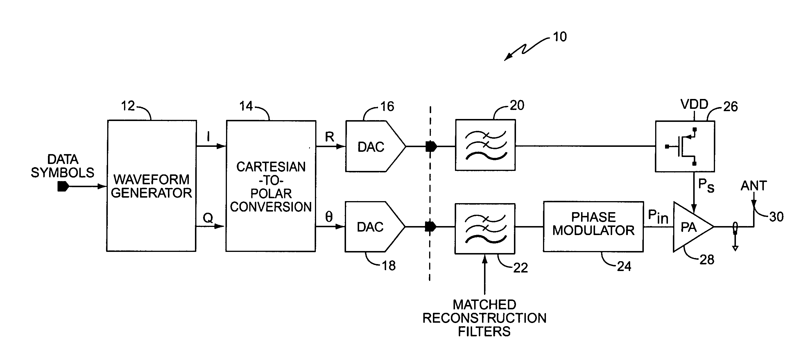
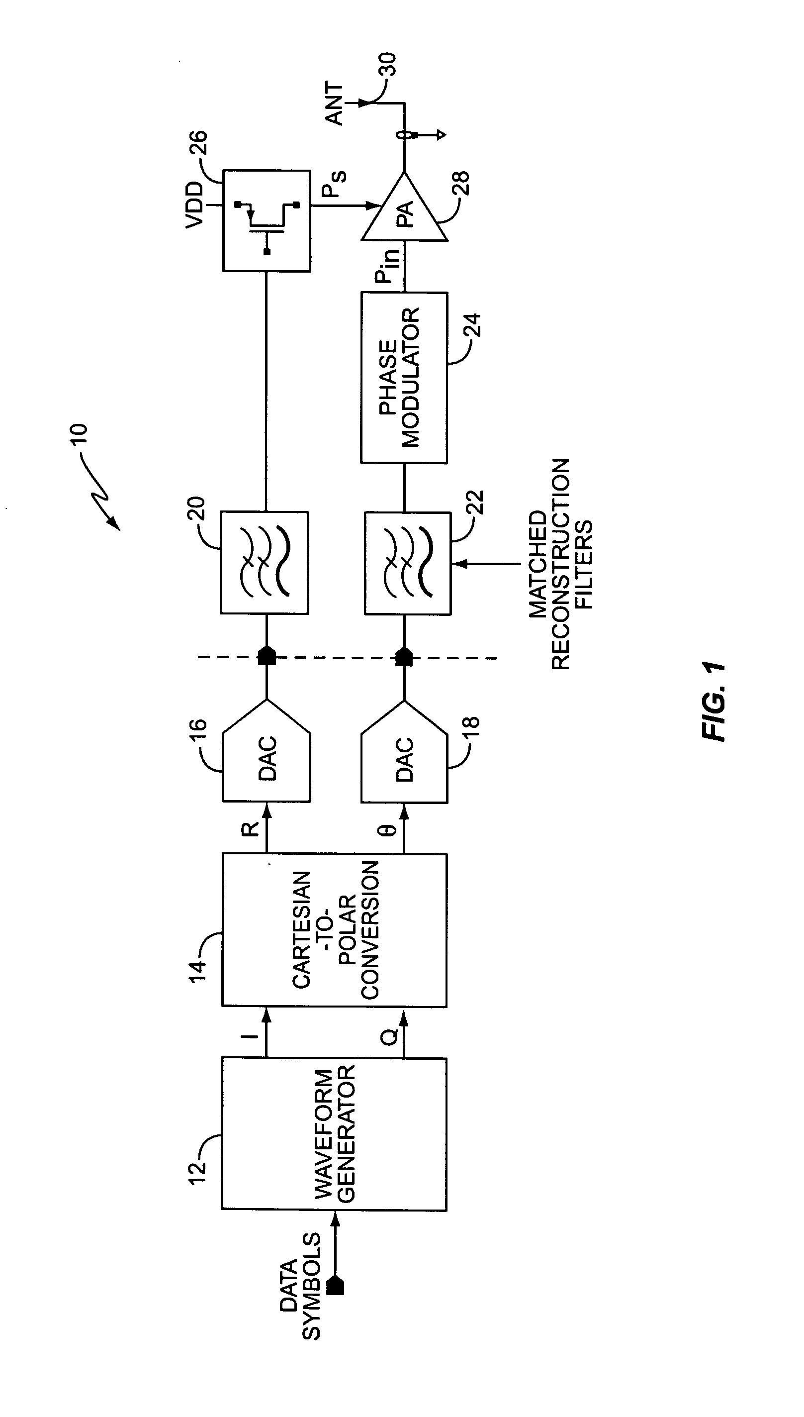
[0025]FIG. 1 illustrates a block diagram of a conventional polar modulation transmitter 10. Polar modulation transmitter 10 includes a waveform generator 12, Cartesian-to-Polar converter 14, digital-to-analog converters (DACs) 16, 18, filters 20, 22, phase modulator 24, regulator 26, power amplifier 28, and antenna 30. Waveform generator 12 generates in-phase (I) and quadrature-phase (Q) output signals responsive to the data input symbols. Cartesian-to-Polar converter 14 extracts the amplitude of the IQ signals according to Equation (2).

R=√{square root over (I2+Q2)}  (2)

Cartesian-to-Polar converter 14 also generates a phase signal θ that represents the original IQ phase information with constant amplitude according to Equation (3). θ=arctan⁡(QI)(3)

It will be appreciated by those skilled in the art that phase signal θ may be separated into I and Q phase components, φI and φQ, where Equation (4) shows the relationship between θ and φI and φQ.

φI=cos(θ)

φQ=sin(θ)   (4)

For simpli...


PUM


Abstract

A method and apparatus for dynamically compensating for delay mismatch between a supply signal and an input signal of a power amplifier in polar modulation transmitters. One exemplary polar modulation transmitter according to the present invention comprises a power amplifier, a phase modulator, a regulator, a delay tracking circuit, and a delay circuit. The phase modulator derives the amplifier input signal responsive to one or more phase signals, while the regulator derives the amplifier supply signal responsive to an amplitude signal. Based on the amplitude signal and the amplifier supply signal, the delay tracking circuit tracks an observed amplitude path delay. The delay circuit adjusts a path delay associated with the phase signal, responsive to the observed amplitude path delay, to compensate for the delay mismatch.

Description

BACKGROUND OF THE INVENTION [0001] The present invention relates generally to polar modulation transmitters, and more particularly to dynamic compensation for delay mismatch between amplitude and phase signals of polar modulation transmitters. [0002] Due to packet switched data traffic and the need for increased data rates for wide-area wireless connections, a GPRS (General Packet Radio Service) standard was developed to enable transmission of packet data using existing GSM (Global System for Mobile communication) networks. As a result, GPRS mobile terminals may continue to use the relatively constant-envelope transmitter chains typically used for GSM. In addition, to obtain higher bit-rates for EDGE (Enhanced Data rates for GSM Evolution) service, the modulation format was changed from GMSK (Gaussian pre-filtered Minimum Shift Keying) to the more bandwidth efficient (3π / 8)-8PSK (8-ary Phase Shift Keying with 3π / 8 symbol-to-symbol phase rotation) with a pre-filtering function that e...

Claims


Application Information

Patent Timeline
IPC IPC(8): H04B1/02
CPCH04L7/0337H04L7/0041H04L27/361
Inventor KLEMMER, NIKOLAUS
Owner TELEFON AB LM ERICSSON (PUBL)
Why Eureka
Try Eureka