Energy application with inflatable annular lens

a technology of annular lens and energy application, which is applied in the field of medical procedures, can solve the problems of stenosis of pulmonary vein or thrombosis, formation of blood clots, scars extending along the path, etc., and achieves the effects of convenient ablation or other thermal treatment, efficient and precise thermal treatment, and rapid heating of a ring-like portion

Inactive Publication Date: 2006-03-16
BOSTON SCI SCIMED INC +1
View PDF99 Cites 85 Cited by
  • Summary
  • Abstract
  • Description
  • Claims
  • Application Information

AI Technical Summary

Benefits of technology

[0011] One aspect of the invention provides apparatus for applying energy to tissue within the body of a living subject as, for example, tissues surrounding the wall of a tubular anatomical structure. Apparatus according to this aspect of the invention includes an ultrasonic emitter having an emitting surface generally in the form of a surface of revolution about a central axis and an inflatable lens surrounding the ultrasonic emitter. The lens has a refractive surface generally in the form of a surface of revolution about the central axis when the lens is inflated. In operation, at least some of the ultrasonic energy, and preferably most or all of the ultrasonic energy emitted at the emitting surface will be directed through the refracted surface of the lens and directed into an annular region surrounding the central axis. The annular region most preferably has an axial extent less than the axial extent of the emitting surface. The power emitted over substantially the entire axial extent of the emitting surface will be directed into the annular region and thus focused in the annular region to provide effective thermal treatment. Focusing the energy promotes rapid heating and minimizes collateral damage to the neighboring tissues.
[0013] The lens and emitter may be arranged to place the focal region within the wall or other tissue surrounding the tubular structure, so that the ultrasonic energy comes to a focus in the tissue rather than at the surface of the wall. Placing the focus within the tissue, rather than at the surface of the tissue, minimizes scarring at the surface and also promotes rapid heating.
[0014] Alternatively, the apparatus may be arranged to direct sonic energy outwardly from the focal region in a collimated generally disc-shaped pattern. As described in detail below, this requires at least two interfaces. The first interface, at the surface of the lens, refracts the ultrasonic waves axially inwardly, toward the plane of an annular focal region, whereas the second interface refracts the inwardly directed to a substantially radially direction. Such a radial, collimated pattern provides relatively high sonic intensity over a substantial depth into the surrounding tissue. This facilitates formation of a thermally treated region having sufficient depth as, for example, an ablated region extending entirely through the wall of a pulmonary vein or the pulmonary vein ostium to assure reliable interruption of the abnormal conductive paths present in atrial fibrillation. A radially-extensive pattern also facilitates ablation or other thermal treatment where the anatomical structure is not precisely round or where the lens and the emitter cannot be positioned precisely concentric with the anatomical structure.
[0016] As discussed above in connection with the apparatus, focusing of the sound into an annular region of a relatively small axial extent concentrates the sonic energy and permits efficient and precise thermal treatment. In particular, concentration of the sonic energy into a relatively small axial region facilitates rapid heating of a ring-like portion of tissue surrounding the anatomical structure. This facilitates ablation or other thermal treatment in such a ring-like region and helps to limit undesired heating of adjacent tissues. Methods according to this aspect of the invention can be used for ablation of the pulmonary vein or pulmonary vein ostium to treat atrial fibrillation, for treatment of the prostate, and for other conditions.

Problems solved by technology

This causes formation of a scar extending along the path where disruption occurred.
This or other factors can lead to stenosis of the pulmonary vein or thrombosis, i.e., formation of blood clots.

Method used


Image

  • Energy application with inflatable annular lens
  • Energy application with inflatable annular lens
  • Energy application with inflatable annular lens

Examples


Embodiment Construction

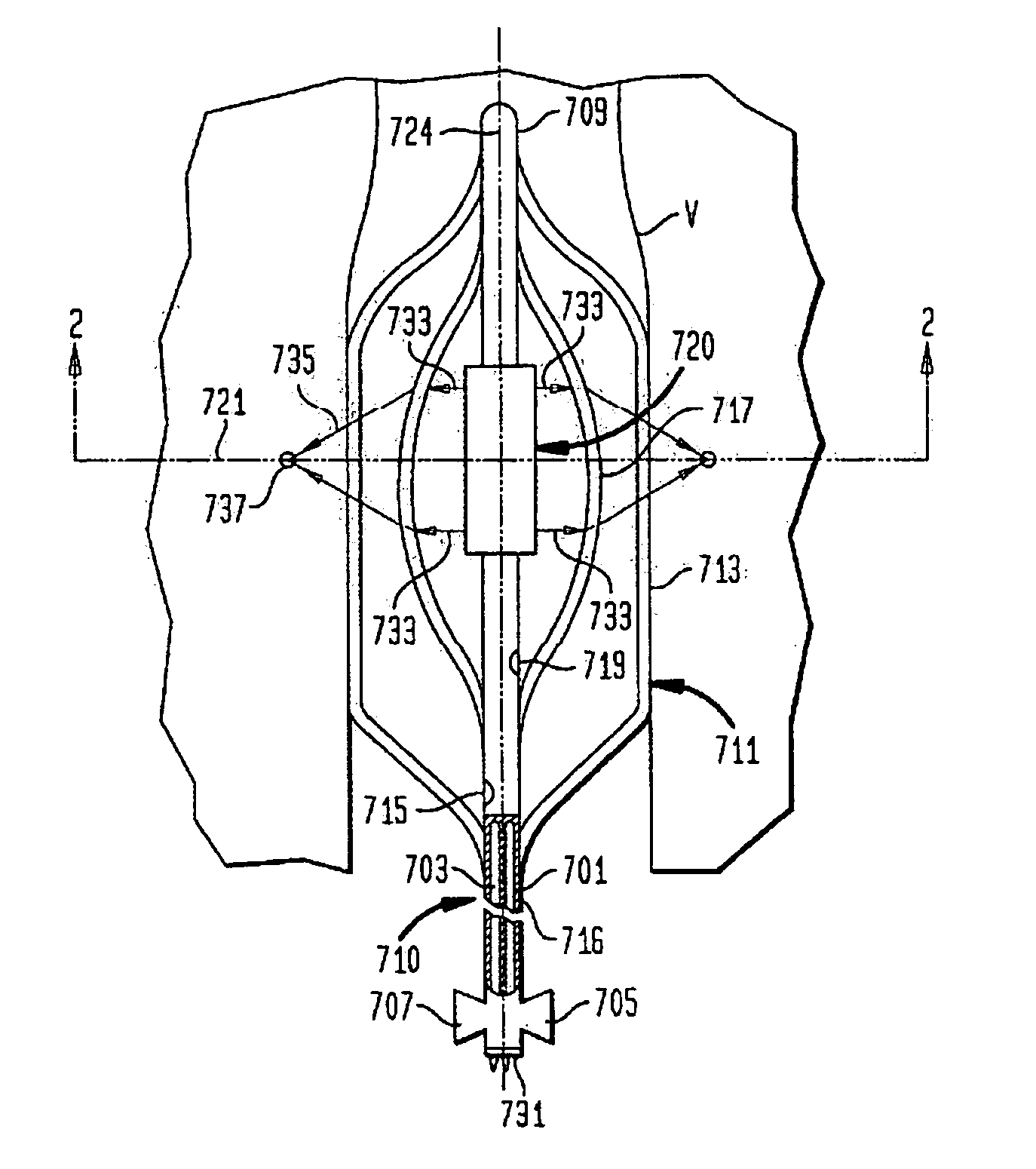
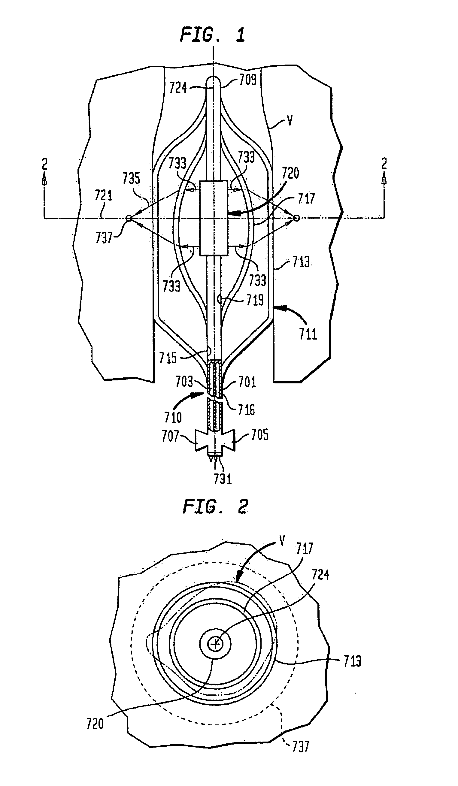
[0025] Apparatus according to one embodiment of the invention (FIGS. 1 and 2) includes a probe structure 710 incorporating a single multi-lumen catheter 716. A first fitting 705 at the proximal end of the catheter communicates with lumen 701 whereas another fitting 707 at the proximal end of the catheter communicates with lumen 703. An emitting element 720 having an emitting surface generally in the form of a surface of revolution is mounted to catheter 716 adjacent the distal end 709 of the catheter. The emitting element defines a medial plane 721 perpendicular to central axis 724 midway between the proximal and distal ends of the emitting element. A bearing balloon 711 surrounds the emitting element. The bearing balloon is formed from a flexible material such as a polymer. Materials similar to those used to form noncompliant balloons in the angioplasty art, such as films of PET, PETG, nylon, polyurethane, polyethylene and other polymers can be used. Typically, such balloons are in...


PUM


Abstract

Apparatus and methods for ablating tissue surrounding a tubular anatomical structure such as the wall of a blood vessel or prostatic tissue surrounding the urethra. The apparatus includes an ultrasonic emitter such as a cylindrical emitter and an inflatable annular lens balloon surrounding the ultrasonic emitter. The lens balloon is inflated with a liquid having acoustic velocity different than that of the surrounding medium, so as to form an annular refracting surface. The acoustic energy from the emitter is focused into an annular focal region.

Description

CROSS-REFERENCE TO RELATED APPLICATIONS [0001] The present application is a continuation of U.S. patent application Ser. No. 09 / 904,963, filed Jul. 13, 2001, which application claims the benefit of the filing date of U.S. Provisional Patent Application No. 60 / 218,641, filed Jul. 13, 2000, the disclosures of which are hereby incorporated by reference herein.FIELD OF THE INVENTION [0002] The present application relates to medical procedures such as hyperthermia, and to apparatus adapted for use these and other procedures. BACKGROUND OF THE INVENTION [0003] In certain medical procedures, it is desirable to heat tissue surrounding a tubular anatomical structure such as a blood vessel or a gastrointestinal, urinary, genital, or respiratory structure. Depending upon the condition to be treated, energy may be applied to the tissue constituting the wall of the structure, or to tissue surrounding the wall. Energy may be applied to heat the tissue to a degree sufficient to cause death of the ...

Claims


Application Information

Patent Timeline
Patent Type & Authority Applications(United States)
IPC IPC(8): A61H1/00A61B18/00A61B17/00A61B17/22A61B18/24A61F7/00A61F7/12A61M25/00A61N7/02
CPCA61B17/2202A61B17/2251A61B18/1492A61B18/24A61B2017/00274A61B2017/22024A61B2017/22027A61B2017/22068A61B2018/00214A61B2018/00547A61M2025/1059A61N7/022
Inventor HARHEN, EDWARD PAULFJIELD, TODDLOPATH, PATRICK DAVIDACKER, DAVID E.
Owner BOSTON SCI SCIMED INC
Why Eureka
Try Eureka