Tool

a hip resurfacing and tool technology, applied in the field of tools, can solve the problems of re-formation of bone, end up unable to function, and further erosion, and achieve the effect of improving the stability of the jig and facilitating accurate cutting

Inactive Publication Date: 2006-03-16
FINSBURY DEV
View PDF12 Cites 40 Cited by
  • Summary
  • Abstract
  • Description
  • Claims
  • Application Information

AI Technical Summary

Benefits of technology

[0027] The body may include an elongated cannulated rod extending upwardly from the body such that the bore of the cannulated rod cooperates with the aperture in the body to improve the stability of the jig on the guide wire. For ease of storage, the cannulated bore may be telescopic.
[0028] The aperture and any bore in the cannulated rod may be sized not only to connect over a guide wire but also to enable the jig to be placed over the guide rod which will be inserted into the enlarged bore in the femoral head during the machining process. This will enable the jig of the present invention to be used as a further check once the femoral head has been inserted which may be after the head has been resected. In an additional or alternative arrangement, the central portion of the slidable telescopic cannulated rod enables the size of the bore of the cannulated rod to be adjusted. Thus when the central rod is in position, the bore will be an appropriate size to su...

Problems solved by technology

Diseases such as rheumatoid- and osteo-arthritis can cause erosion of the cartilage lining of the acetabulum so that the ball of the femur and the hip bone rub together causing pain and further erosion.
Bone erosion may cause the bones themselves to attempt to compensate for the erosion which may result in the bone being reshaped.
This misshapen joint may cause pain and may eventually cease to function alt...

Method used


Image

  • Tool
  • Tool
  • Tool

Examples


Embodiment Construction

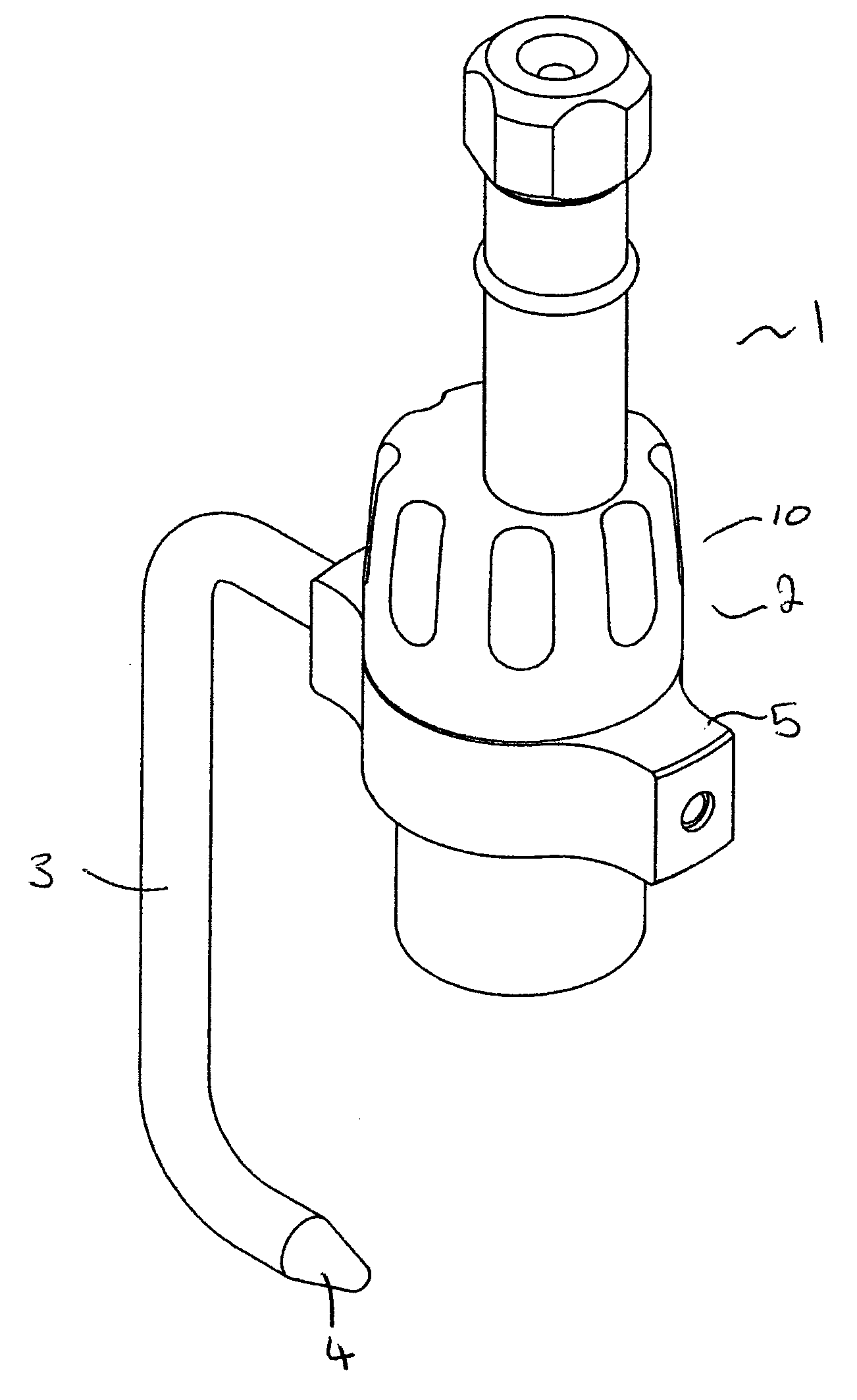
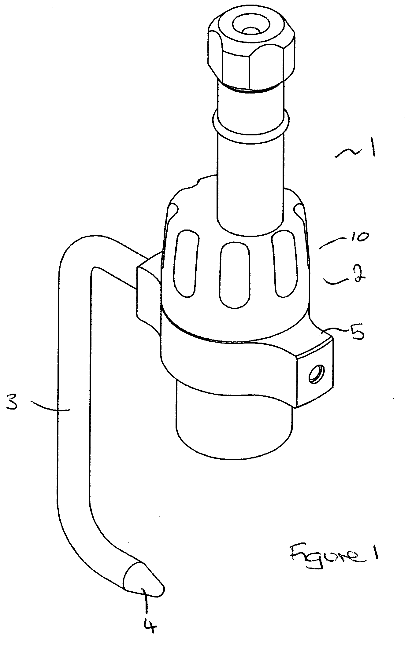
[0040] As illustrated in FIG. 1, the jig 1 of the present invention includes a body 2 having an arm 3 extending therefrom. A tip 4 is located at the free end of the arm.

[0041] In the illustrated arrangement the body comprises a collar 5 in which the rotating component 10 which is a jog dial is placed.

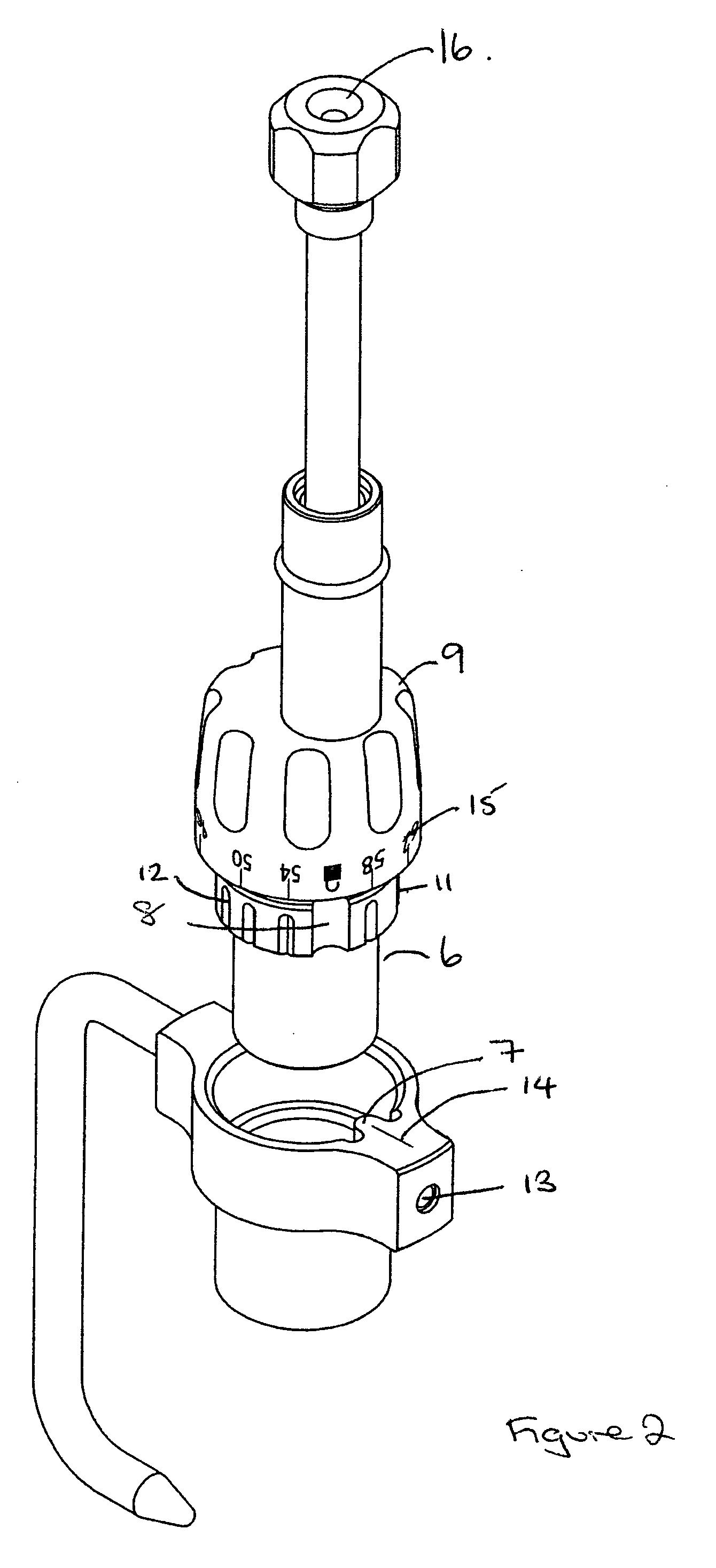
[0042] As illustrated in FIG. 2 the jog dial comprises a seating member 6. A ring 11 is located around the seating member and includes spaced around its periphery a selection of indexing slots 12. A release slot 8 is provided which will be aligned to a stop 7 in the collar which allows the jog dial to be inserted and removed. When the jog dial is rotated, the release slots 12 interlock in turn with a spring ball grub screw (not shown) which is located in an aperture 13 in the collar. A set radius locator 14 is provided on the collar and the user will select the required position by lining up the selected portion with the locator. Indicia 15 are marked around the jog dial.

[0043] An ap...


PUM


Abstract

A checking jig comprising: a body having an aperture therethrough which in use can be placed over a guide wire located in a well in the head of the femur; an arm extending from the body and shaped to extend around the head of the femur; a tip located on the end of the arm remote from the body said tip representing the diameter at which a particular size of sleeve cutter will cut; and means for adjusting the position of the tip between different positions representing different cut diameters.

Description

BACKGROUND OF THE INVENTION [0001] The present invention relates to a tool for use in hip resurfacing operations. More particularly, it relates to a checking jig which may be used to verify the correct positioning and size of sleeve cutter to be used in machining the head of a femur. [0002] The efficient functioning of the hip joints is extremely important to the well being and mobility of the human body. Each hip joint is comprised by the upper portion of the upper leg bone (femur) which terminates in an offset bony neck surmounted by a ball-headed portion which rotates within a socket, known as the acetabulum, in the pelvis. Diseases such as rheumatoid- and osteo-arthritis can cause erosion of the cartilage lining of the acetabulum so that the ball of the femur and the hip bone rub together causing pain and further erosion. Bone erosion may cause the bones themselves to attempt to compensate for the erosion which may result in the bone being reshaped. This misshapen joint may caus...

Claims


Application Information

Patent Timeline
IPC IPC(8): A61B17/60A61B17/16A61B17/17A61B19/00A61F2/46
CPCA61B17/1668A61B17/175A61F2002/4659A61B2019/461A61B19/46A61B90/06A61B2090/061
Inventor WOZENCROFT, ROBERT MICHAELTUKE, MICHAEL ANTHONY
Owner FINSBURY DEV
Why Eureka
Try Eureka