Hammer drill

a hammer drill and drill bit technology, applied in the field of hammer drills, can solve the problems of tool bits chipping or chiseling away at the workpiece, and achieve the effect of improving the accuracy and accuracy of the hammer drill bi

Active Publication Date: 2006-03-23
BLACK & DECKER INC
View PDF40 Cites 35 Cited by
  • Summary
  • Abstract
  • Description
  • Claims
  • Application Information

AI Technical Summary

Problems solved by technology

However, the tool bit is capable of axially sliding within the tool holder over a limited range of movement.
The striker repeatedly hits end of the tool bit within the tool holder, causing tool bit to chip or chisel away at the work piece.

Method used


Image

  • Hammer drill
  • Hammer drill
  • Hammer drill

Examples


Embodiment Construction

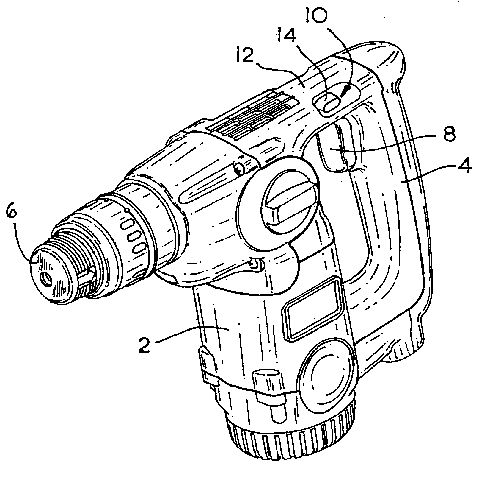
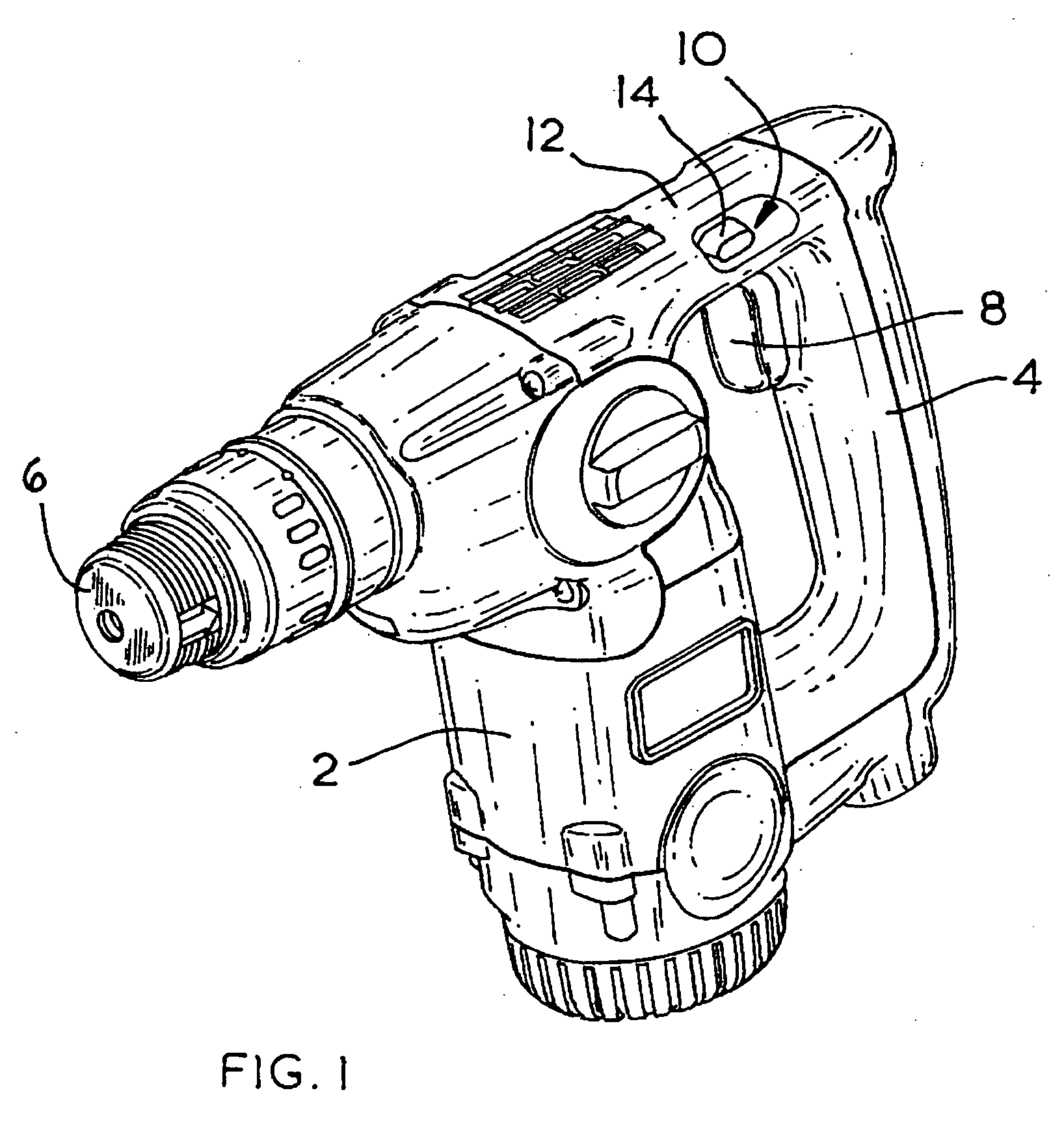
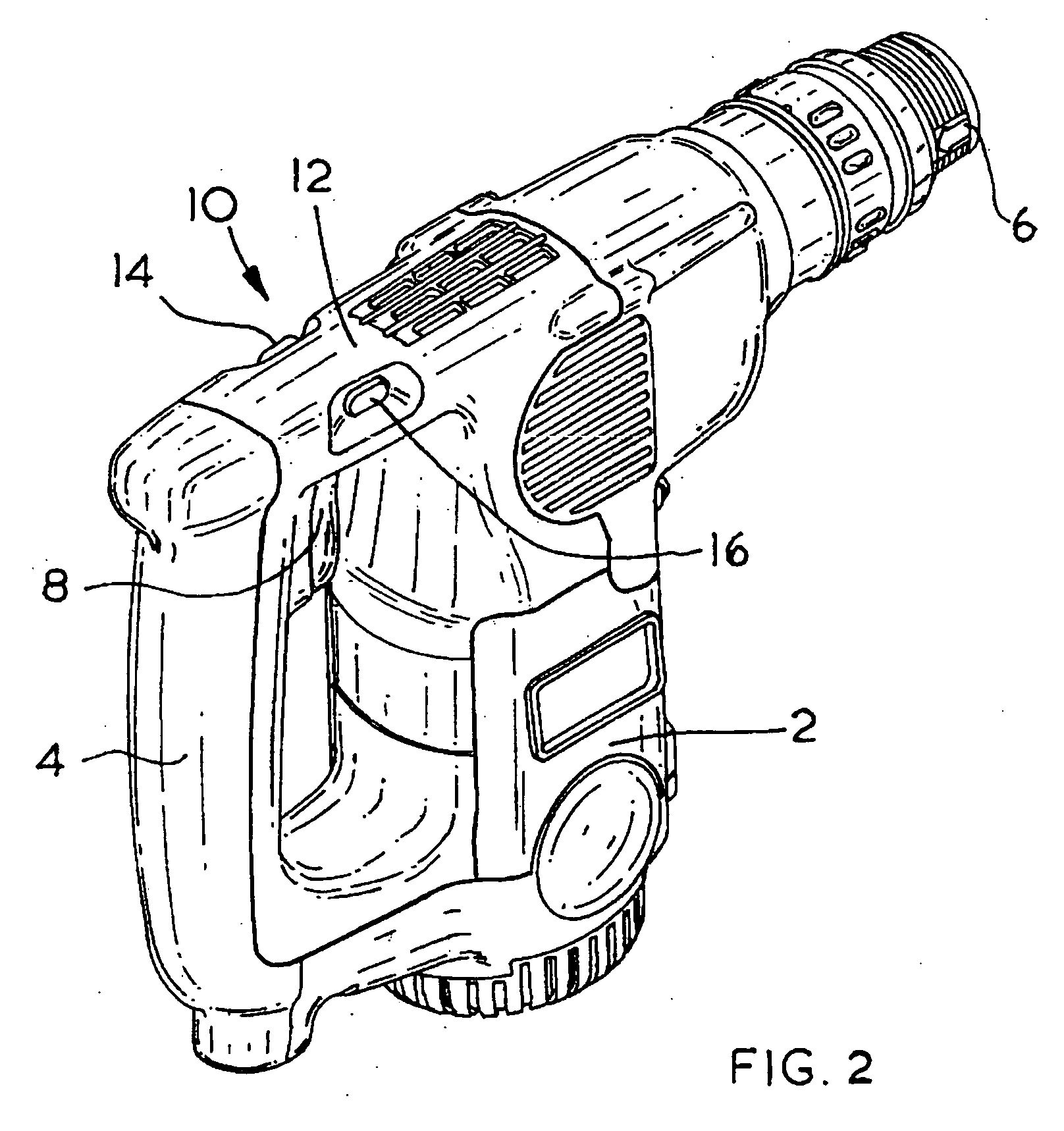
[0025] Referring to FIGS. 1 and 2, the chipper comprises a body 2 attached to the rear of which is a rear support handle 4. An electric motor (not shown) is mounted within the body. The electric motor is powered by a mains electricity power supply (not shown).

[0026] Mounted on the front of the body 2 of chipper is a tool holder 6. A chisel (not shown) can be mounted in the tool holder 6. The tool holder prevents the chisel from rotation. However, the chisel is capable of axially sliding within the tool holder 6 over a limited range of movement.

[0027] The electric motor is activated by depression of a trigger button 8 which is mounted on the inside of the rear support handle 4. The electric motor reciprocatingly drives a striker (not shown) via gears (not shown) and a wobble bearing (not shown) and an air spring in the form of a piston, cylinder and ram (not shown) mounted within the body 2 of the chipper in well-known manner. The striker repeatedly hits the end of a chisel located...


PUM

PropertyMeasurementUnit
external forceaaaaaaaaaa
biasing forceaaaaaaaaaa
sliding movementaaaaaaaaaa

Abstract

A hammer drill, in particular a chipper comprising: a body 2 having at least one support handle 4; an electric motor mounted within the body 2; an electric switch 22, capable of being switched on and off by a trigger button 8 connected to it, to activate or deactivate respectively the electric motor, wherein the trigger button 8 is moveable between two positions, a first position where the electric switch 22 is off and a second position where the electric switch 22 is on; a locking arm 38 moveably mounted on the electric switch 22 which, when the trigger button 8 is located in its second position, is moveable between two positions, a first position where it is disengaged from the trigger button 8 and a second position where it engages with the trigger button 8 and holds the trigger button 8 in its second position. When the locking arm is in its second position it causes the hammer to remain switch on even if the operator removes their fingers from the trigger button.

Description

FIELD OF THE INVENTION [0001] The present invention relates to a hammer drill and in particular, a chipper. BACKGROUND OF THE INVENTION [0002] A chipper is a power tool which is used to chisel a workpiece such a block of stone. Typically, such chippers are powered by an electric motor which are either powered by a mains electricity power supply or by a battery. A tool bit, usually in the form of a chisel, is mounted in a tool holder located at the front of the chipper. The tool holder prevents the tool bit from rotation. However, the tool bit is capable of axially sliding within the tool holder over a limited range of movement. [0003] The electric motor is activated by depression of the trigger switch which is usually mounted on a handle attached to the body of the chipper. The electric motor reciprocatingly drives a striker via gears, a rotary to linear movement conversion mechanism, typically a crank or wobble bearing, and an air spring, typically in the form of a piston, cylinder...

Claims


Application Information

Patent Timeline
Patent Type & Authority Applications(United States)
IPC IPC(8): B23B45/00
CPCB25D17/00B25D2250/091H01H13/08H01H3/20H01H9/06B25D2250/261
Inventor KUNZ, MICHAEL
Owner BLACK & DECKER INC
Why Eureka
Try Eureka