Majority voter apparatus, systems, and methods

a technology of majority voters and circuits, applied in pulse generators, pulse techniques, instruments, etc., can solve problems such as increasing circuit complexity and consuming significant static power

Inactive Publication Date: 2006-03-23
INTEL CORP
View PDF2 Cites 10 Cited by
  • Summary
  • Abstract
  • Description
  • Claims
  • Application Information

AI Technical Summary

Problems solved by technology

Such solutions may consume significant static power, and using a reference voltage source may increase circuit complexity.

Method used


Image

  • Majority voter apparatus, systems, and methods
  • Majority voter apparatus, systems, and methods
  • Majority voter apparatus, systems, and methods

Examples


Embodiment Construction

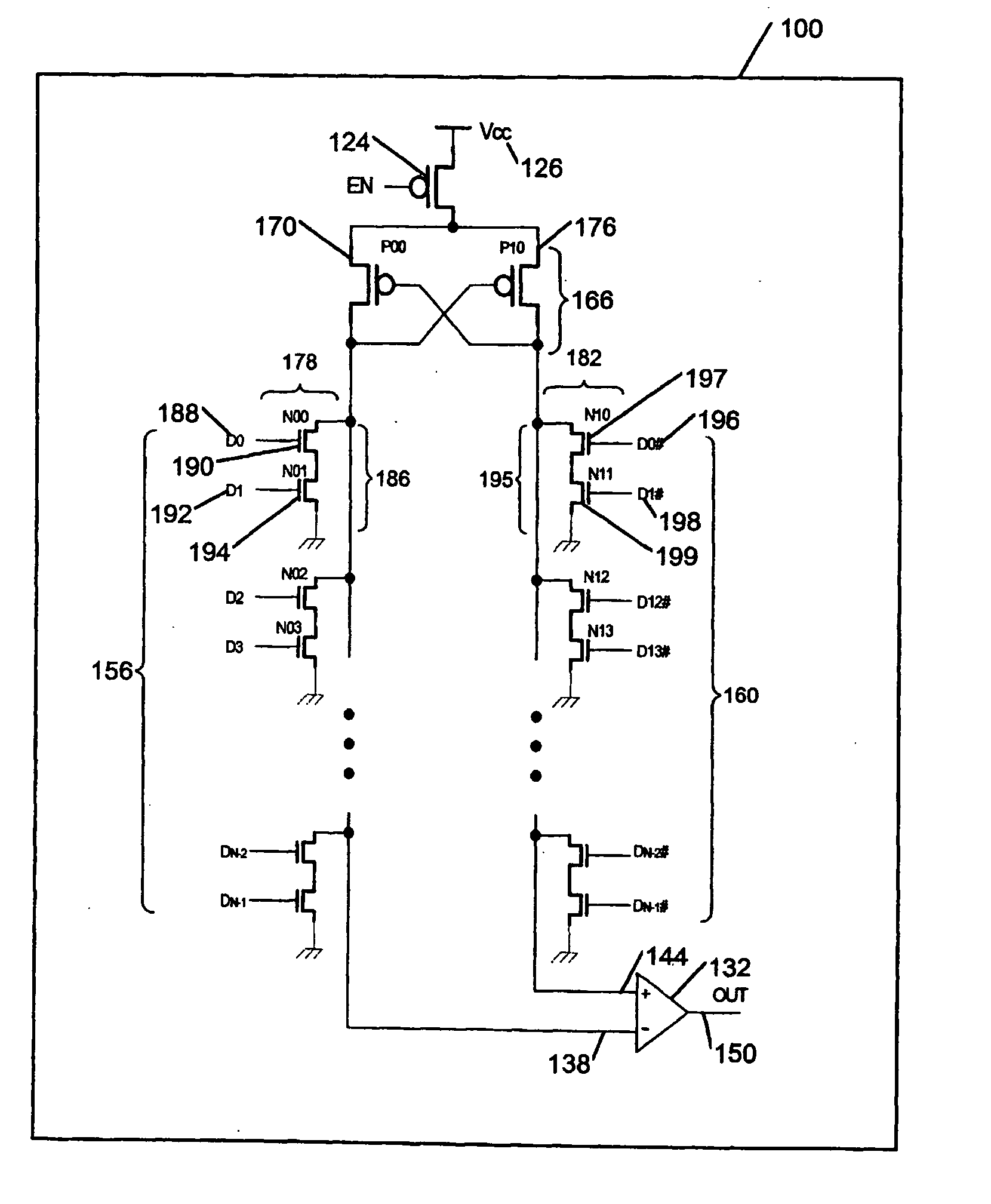
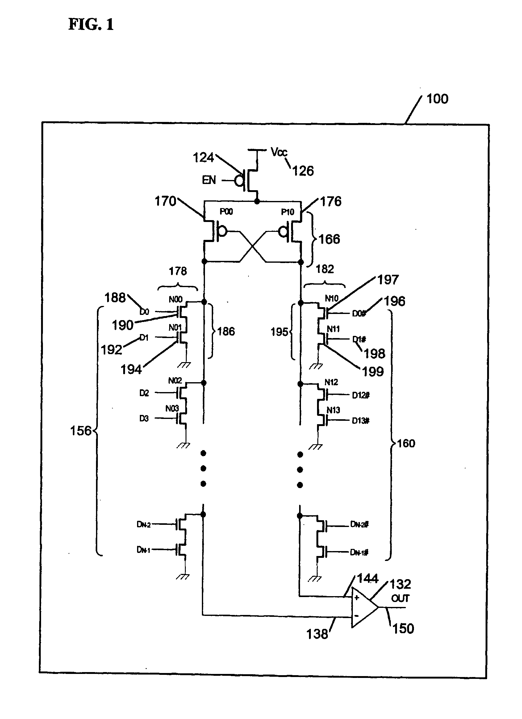
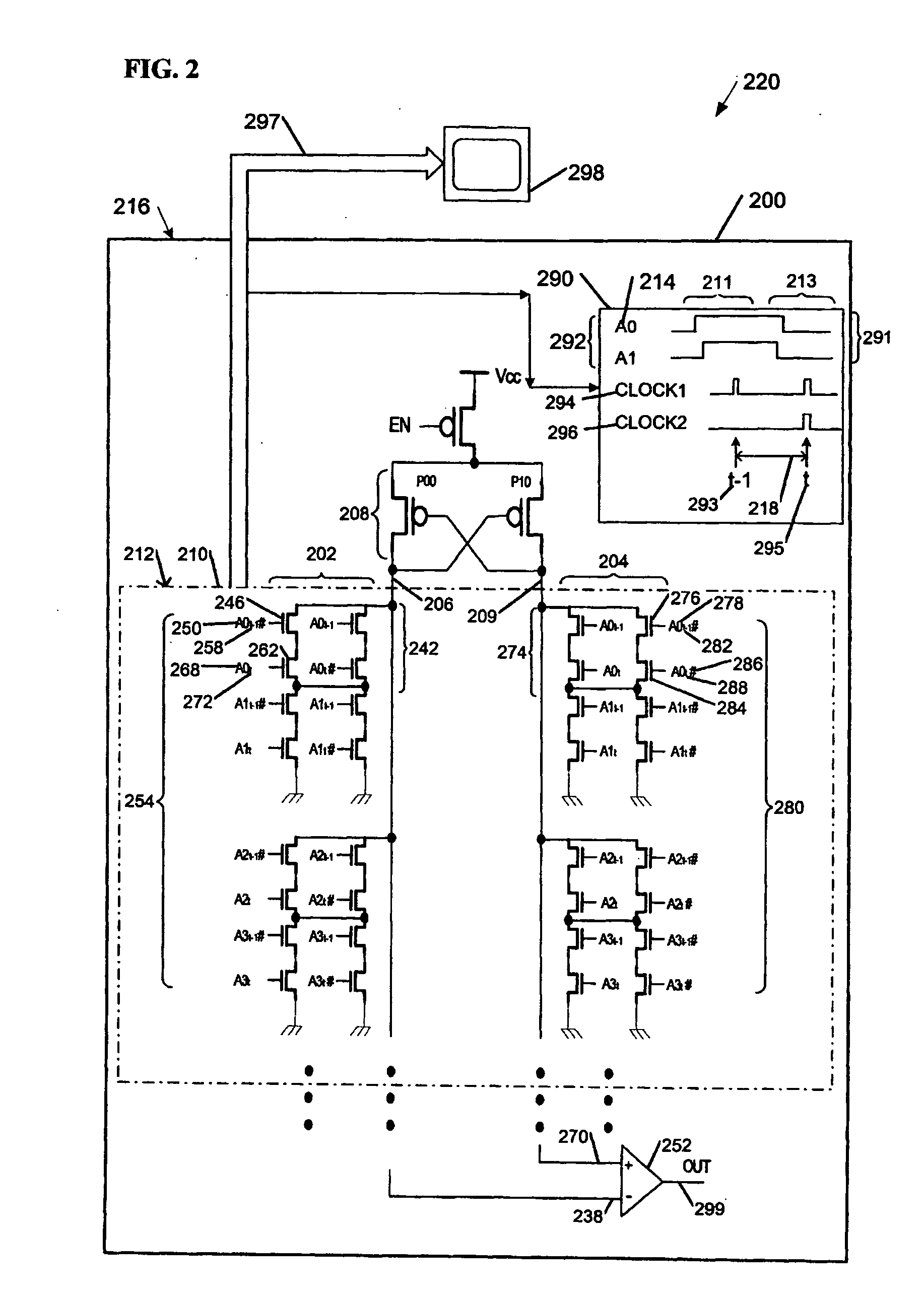
[0008] Various embodiments disclosed herein attempt to reduce circuit complexity and / or static power consumption in majority voter apparatus. In some embodiments, input bits participating in a “vote” may be coupled to a voltage divider network that may include branches of transistors coupled to each of two legs of a cross-coupled pair of transistors in series between a voltage source and a sense amplifier. “Voting” in the current context means determining whether a group of input bits comprises more bits set to a logical “one” or more bits set to a logical “zero,” and / or providing a single-bit indication thereof.

[0009] Static current through the voltage divider may be partially avoided by employing a transistor in series between the voltage source and the cross-coupled pair of transistors, and by enabling this series transistor at a time of voting. In some embodiments, it may be useful to match the transistors in both branches, perhaps by using devices having relatively long channe...


PUM


Abstract

Apparatus and systems, as well as methods and articles, may operate to provide a majority voter indication using a sense amplifier coupled to a first plurality of bit inputs and to a second plurality of bit inputs.

Description

TECHNICAL FIELD [0001] Various embodiments described herein relate to digital circuits generally, including apparatus, systems, and methods used to communicate binary data. BACKGROUND INFORMATION [0002] Parallel data paths including buses may be used to communicate binary information. In the course of data transfer across a bus, it may be desirable to determine whether the majority of bits on the bus are in a specified condition (e.g., set or reset “majority voter” status). [0003] Some majority voter methods may employ a cascade of logic gates to count the number of bit inputs in a set condition from a small group of bit inputs (e.g. two-of-three counters), and to sum the output of the cascade. The number of gates required to implement this solution may increase geometrically with bus width. Analog majority voter methods may resistively couple bit inputs to an operational amplifier input, and couple a voltage source to the other operational amplifier input as a reference. Such solut...

Claims


Application Information

Patent Timeline
Patent Type & Authority Applications(United States)
IPC IPC(8): H03K19/003
CPCH03K19/23
Inventor YE, YIBINTSCHANZ, JAMES W.KHELLAH, MUHAMMAD M.DE, VIVEK K.
Owner INTEL CORP
Why Eureka
Try Eureka