Voltage supply circuit and microphone unit comprising the same

a technology of voltage supply circuit and microphone unit, which is applied in the direction of electric/magnetic computing, instruments, mouthpiece/microphone attachments, etc., can solve the problem of sensitivity dispersion of each condenser microphone uni

Inactive Publication Date: 2006-03-23
RENESAS ELECTRONICS CORP
View PDF4 Cites 56 Cited by
  • Summary
  • Abstract
  • Description
  • Claims
  • Application Information

AI Technical Summary

Benefits of technology

[0010] According to an aspect of the present invention, a voltage supply circuit comprises a voltage control circuit for outputting a bias voltage control signal according to a set value based on a bias voltage of a sensor and a voltage generation circuit for generating the bias voltage to be applied to the sensor based on the bias voltage control signal.
[0011] According to another aspect of the present invention, a microphone unit comprises a microphone to which bias voltage is supplied a voltage generation circuit for boosting the power supply voltage and generating the bias voltage based on a bias voltage control signal and a voltage control circuit for outputting the bias voltage control signal based on a set value of the bias voltage.
[0012] According to another aspect of the present invention, a sensitivity adjustment method for a microphone unit, which comprises a condenser microphone, an amplification circuit and a voltage supply circuit which supplies a bias voltage based on a set value to

Problems solved by technology

This manufacturing dispersion becomes a cause of the se

Method used


Image

  • Voltage supply circuit and microphone unit comprising the same
  • Voltage supply circuit and microphone unit comprising the same
  • Voltage supply circuit and microphone unit comprising the same

Examples


first embodiment

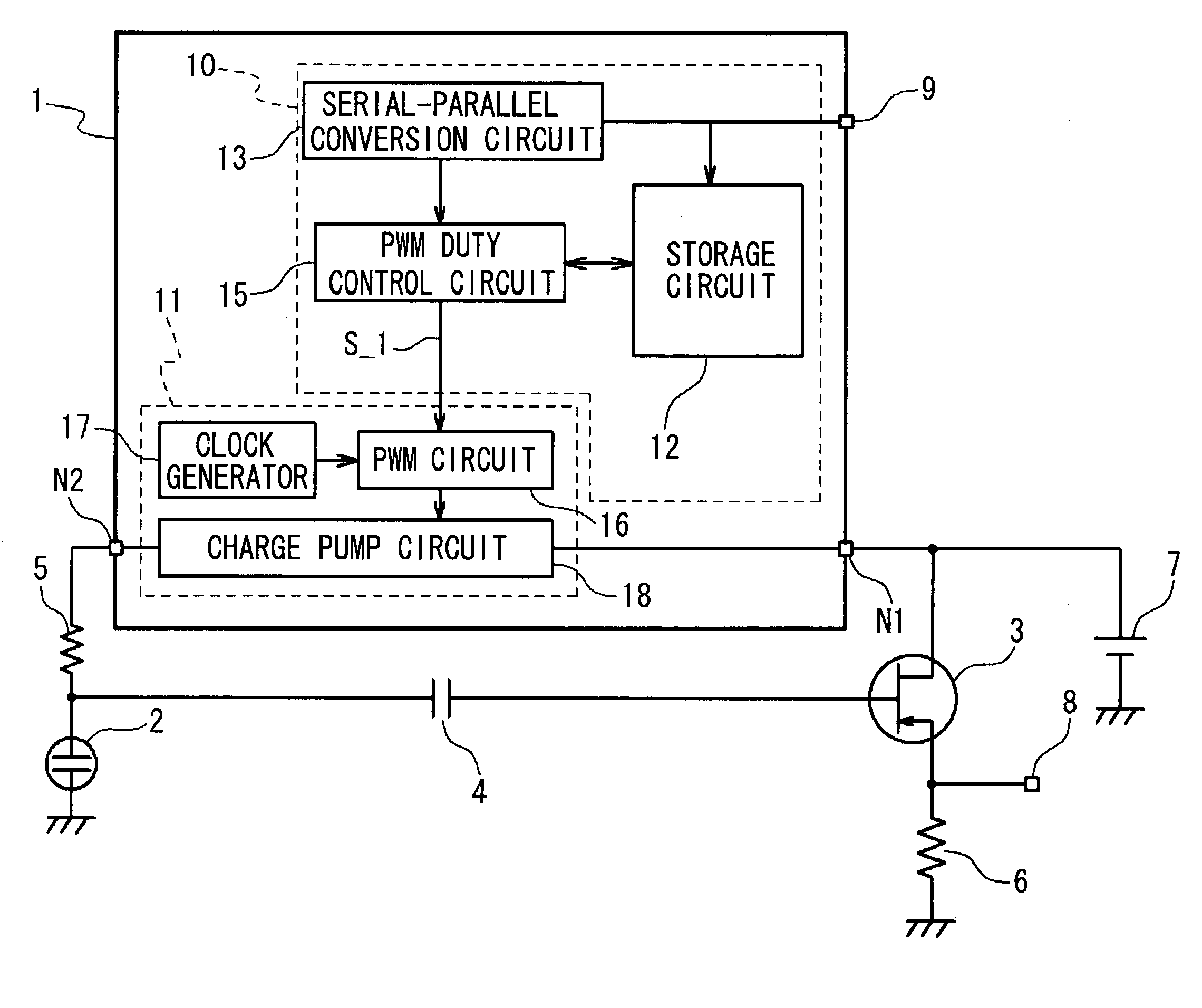
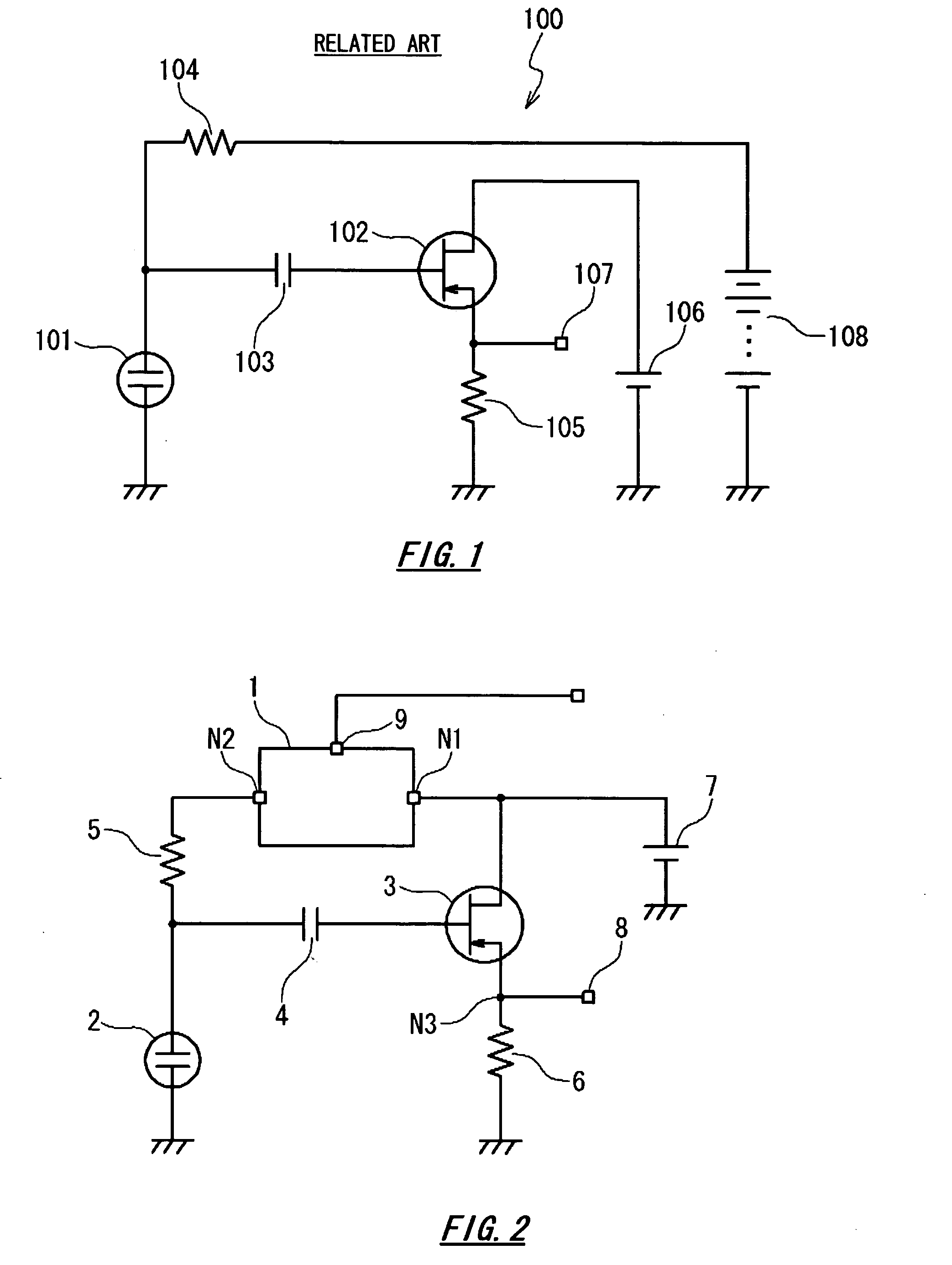
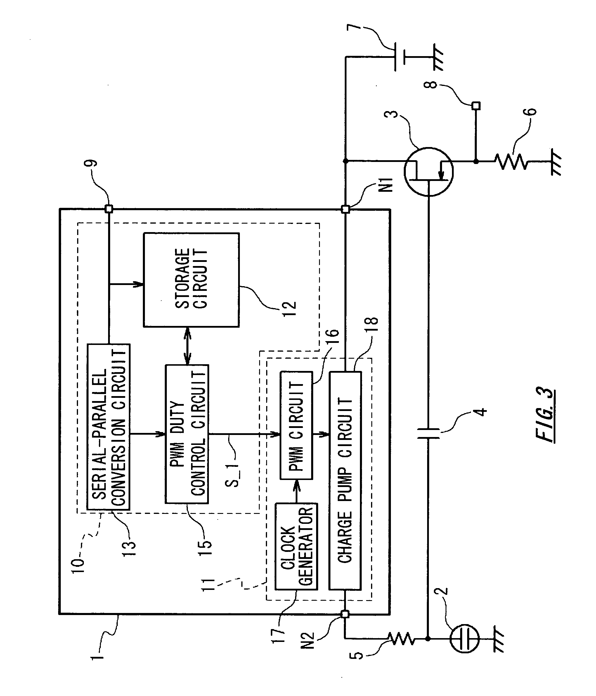
[0036]FIG. 2 is a block diagram depicting the configuration of the microphone unit according to a first embodiment of the present invention. As FIG. 2 shows, the microphone unit according to the first embodiment comprises a voltage supply circuit 1, condenser microphone 2, amplification circuit 3, capacitor 4 and resistors 5 and 6.

[0037] The voltage supply circuit 1 generates the bias voltage so that the sensitivity of the condenser microphone 2 becomes a predetermined sensitivity, and supplies it to the condenser microphone 2. The voltage supply circuit 1 is connected to the power supply 7 via the first node N1. The voltage supply circuit 1 generates the bias voltage based on the power supply voltage of this power supply 7. This bias voltage is output from the second node N2, and is applied to the condenser microphone 2 via the resistor 5.

[0038] The condenser microphone 2 is a type of sensor (vibration sensor). The sensitivity of the condenser microphone 2 is set according to the...

second embodiment

[0087]FIG. 10 is a block diagram depicting a second embodiment of the present invention. In the microphone unit according to the second embodiment, the storage circuit is different from the first embodiment. The storage unit 30 of the second embodiment comprises a plurality of storage areas, the first storage area 30-1-Nth storage area 30-N (N: 2 or higher natural number). Each of the plurality of storage areas stores the set value corresponding to a different sensitivity.

[0088]FIG. 10 is a block diagram depicting the configuration in the sensitivity adjustment according to the second embodiment of the present invention. In the sensitivity adjustment device 20 according to the second embodiment, the reference voltage block 25 is different from the first embodiment. The reference voltage holding block 25 stores a plurality of reference voltage values. The reference voltage block 25 in FIG. 10 comprises two reference voltages to simplify understanding of the present embodiment, but t...

third embodiment

[0103]FIG. 13 is a block diagram depicting the third embodiment of the present invention. The voltage generation circuit 11 according to the third embodiment includes the charge pump stage count switching circuit 34 in the post-stage of the charge pump circuit 33. The voltage control circuit 10 of the third embodiment comprises a storage device 31 and the stage count switching control circuit 32 for controlling the storage device 31 and the charge pump stage count switching circuit 34.

[0104] The charge pump circuit 33 shown in FIG. 13 is a charge pump circuit comprising a plurality of output terminals. The plurality of output terminals of the charge pump circuit 33 are connected to the charge pump stage count switching circuit 34.

[0105] The stage count switching control circuit 32 installed in the voltage control circuit 10 of the third embodiment is a control circuit for instructing the charge pump stage count switching circuit 34 to switch the number of stages of the charge pump...


PUM


Abstract

A voltage supply circuit comprises a voltage control circuit for outputting a bias voltage control signal according to a set value based on a bias voltage of a sensor and a voltage generation circuit for generating the bias voltage to be applied to the sensor based on the bias voltage control signal.

Description

BACKGROUND OF THE INVENTION [0001] 1. Field of the Invention [0002] The present invention relates to a voltage supply circuit for supplying voltage to a sensor such as a condenser microphone, and a microphone unit comprising the same. [0003] 2. Description of the Related Art [0004] For voice communication in portable terminals, such as portable telephones, a technology using a microphone, called a condenser microphone, has been popularized. A condenser microphone is sometimes called a capacitor microphone or an electrostatic microphone. In a condenser microphone, one electrode of a capacitor is a diaphragm. This diaphragm detects the vibration of voice as a change of capacitance, and converts it into electric signals. A conventional microphone unit is disclosed in “PA acoustic system, (Kougakutosho Ltd., 1996)”[0005]FIG. 1 shows a circuit of a condenser microphone unit 100 using a conventional condenser microphone. As FIG. 1 shows, the conventional condenser microphone unit comprise...

Claims


Application Information

Patent Timeline
IPC IPC(8): H04R3/00H03G3/20H03G3/00
CPCH04R3/00H03G3/30H04M1/00H04R1/06H04R1/08H04R19/04
Inventor KINOSHITA, HIROSHIGE
Owner RENESAS ELECTRONICS CORP
Why Eureka
Try Eureka