
Systems and methods for arriving at an auto focus Figure of Merit

a technology of merit and system, applied in the field of imaging, can solve problems such as frame, increase the cost of an edge detector, and inconsistent calculation results

Inactive Publication Date: 2006-03-23
HEWLETT PACKARD DEV CO LP
View PDF9 Cites 62 Cited by
  • Summary
  • Abstract
  • Description
  • Claims
  • Application Information

AI Technical Summary

Benefits of technology

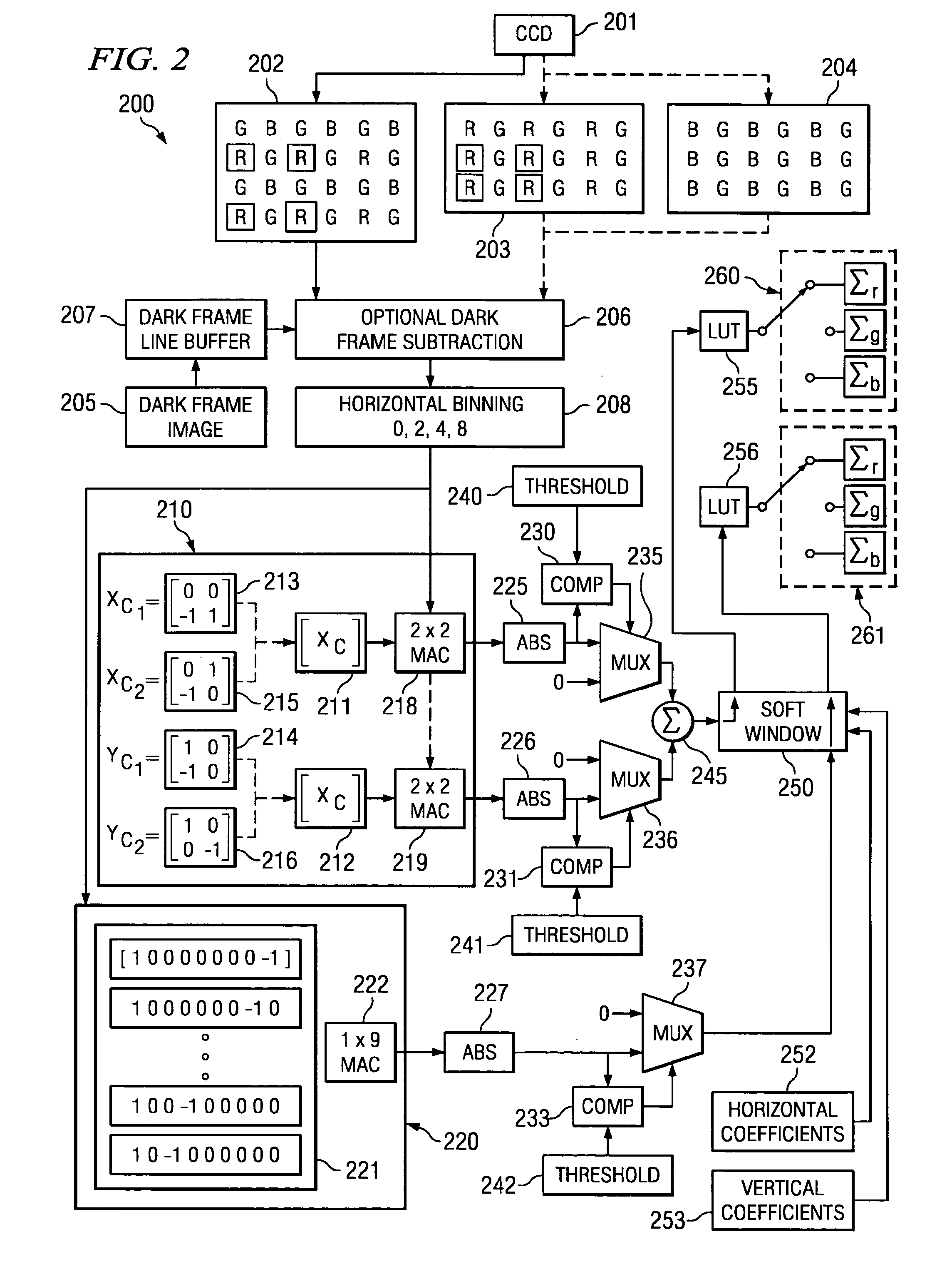
The patent describes a method and system for detecting edges in a captured image. The system includes an edge detector that calculates differences in pixel contrast of adjacent pixels in a focusing region of the image. These differences are then filtered using a comparator and a multiplexer to remove any that are not significant. The system also includes a second edge detector that calculates differences in pixel contrast of non-adjacent pixels in parallel with the first detector. The technical effect of this patent is to improve the accuracy and reliability of edge detection in captured images, which can be useful in various applications such as image processing and computer vision.

Problems solved by technology

Problematically, at the boundary of this region, or focus window, a high contrast edge may move in and out of the focus window between frames, providing inconsistent FOM calculation results, frame to frame.
Depending on the complexity of the edge detector employed multiple line buffers may be required to provide vertical, or diagonal, edge detection, fairly dramatically increasing the cost of an edge detector.

Method used


Image

  • Systems and methods for arriving at an auto focus Figure of Merit
  • Systems and methods for arriving at an auto focus Figure of Merit
  • Systems and methods for arriving at an auto focus Figure of Merit

Examples


Embodiment Construction

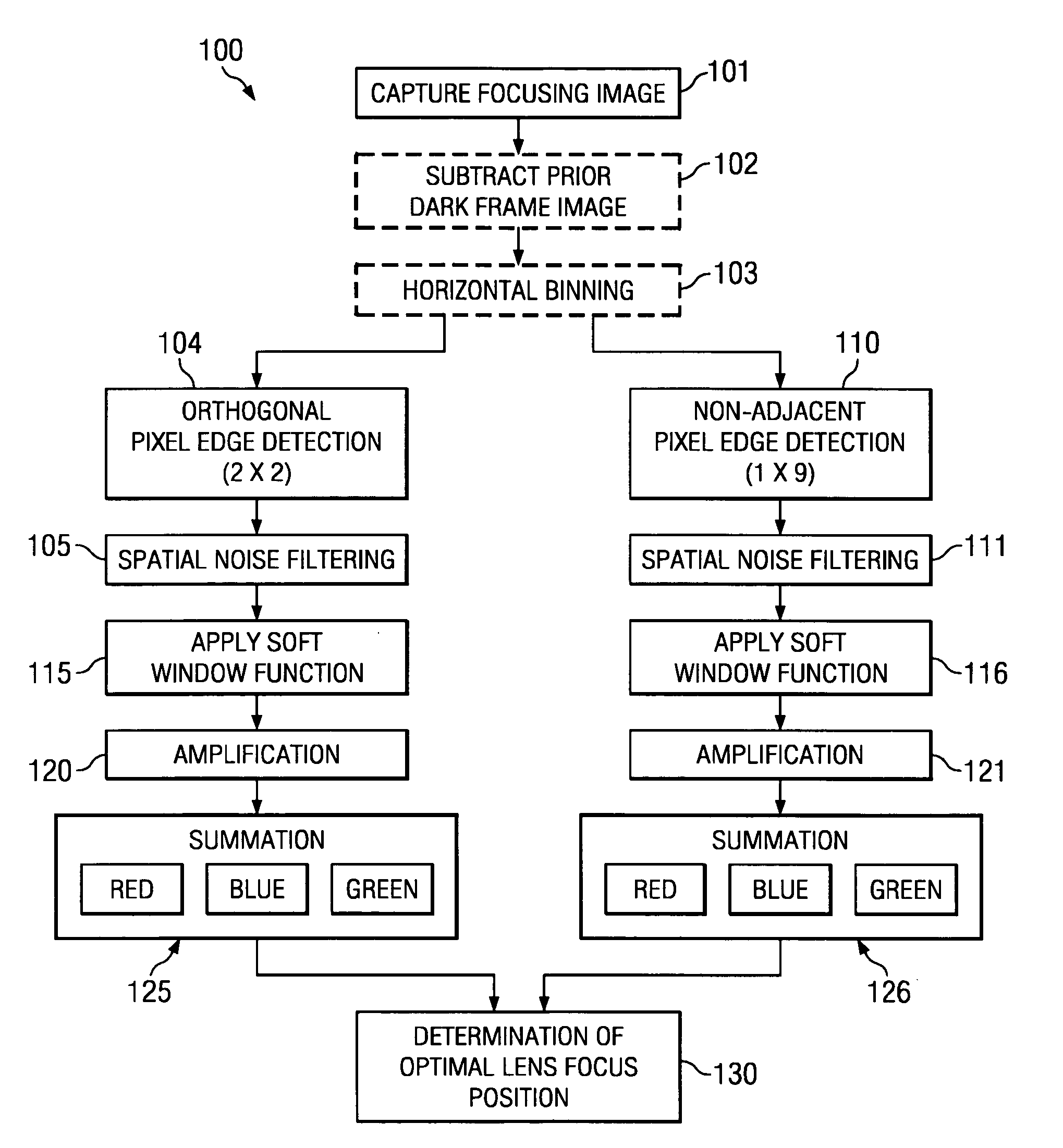
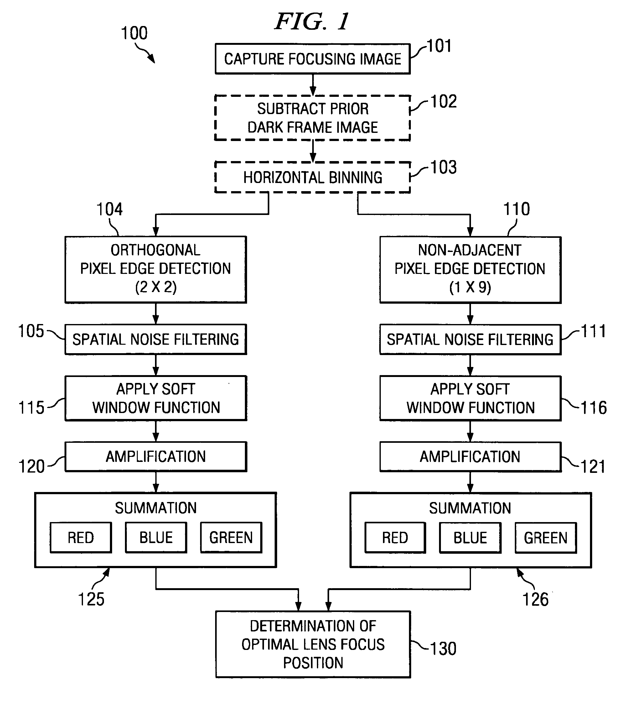
[0010]FIG. 1 is a flow chart of embodiment 100 of a method for arriving at an auto focus Figure of Merit (FOM) for digital cameras. A focusing image is captured at 101 in a manner well known to those of ordinary skill in the art. Embodiments of the present systems and methods may employ a subtraction of a prior dark frame to remove dark noise from a focusing image prior to FOM calculations. Thus, at 102 an optional prior dark frame subtraction is carried out on the image captured at 101. A dark image previously captured with the shutter closed on the CCD gathers whatever electron well collection that is occurring in the absence of the light. Optional prior dark frame subtraction 102 removes a dark image from the CCD captured focusing image. Preferably, the dark frame image that is subtracted from the focusing image was taken at the same exposure settings as the focusing image.

[0011] The present systems and methods may also employ pixel binning to remove focusing image noise, partic...


PUM


Abstract

A method comprises detecting edges in at least a region of a captured focus image, using adjacent pixels of the region to obtain first edge detection results and filtering the first edge detection results. The first filtering comprises comparing differences in pixel contrast in the first edge detection results with a first threshold value and removing the differences in pixel contrast that are less than the first threshold value from the first edge detection results. The method further comprises detecting edges in at least the region, using non-adjacent pixels of the region to obtain second edge detection results and filtering the second edge detection results. The second filtering comprising comparing differences in pixel contrast in the second edge detection results with a second threshold value and removing the differences in pixel contrast that are less than the second threshold value from the second edge detection results.

Description

FIELD OF THE INVENTION [0001] This disclosure is broadly related to imaging and more specifically to systems and methods for arriving at an auto focus Figure of Merit (FOM). DESCRIPTION OF RELATED ART [0002] For digital cameras, focus is typically accomplished using image information captured through the use of the camera's photo sensor, imaging component or light-sensitive integrated circuit, such as an area charge-coupled device (CCD) used to capture images. Use of image information captured by the camera's area CCD eliminates the need and expense for a separate photo sensor dedicated to focusing. By contrast, film cameras typically employ a separate photo sensor, such as a linear CCD, that is used separately for focusing. In performing auto focus calculations or determinations, a common goal is to gather or maximize the contrast between adjacent pixels in the array of pixels captured using an area CCD. The theory behind such use of electronic images for focusing is that a sharp l...

Claims


Application Information

Patent Timeline
Patent Type & Authority Applications(United States)
IPC IPC(8): G06K9/40H04N5/232
CPCH04N5/23212G02B7/36H04N23/673H04N23/84
Inventor AAS, ERIC F.HOFER, GREGORY V.MILLER, CASEY L.
Owner HEWLETT PACKARD DEV CO LP
Learn More