
Structured anode X-ray source for X-ray microscopy

a structured anode and x-ray microscopy technology, applied in the direction of x-ray tube target and convertor, x-ray tube laminated target, etc., can solve the problem of increasing the brightness of this type of source due to the melting of the anode target, the current cost of accelerator and miniature synchrotron source, and the method is limited to soft x-rays, etc. problem, to achieve the effect of improving performan

Active Publication Date: 2008-10-28
CARL ZEISS X RAY MICROSCOPY
View PDF3 Cites 60 Cited by
  • Summary
  • Abstract
  • Description
  • Claims
  • Application Information

AI Technical Summary

Benefits of technology

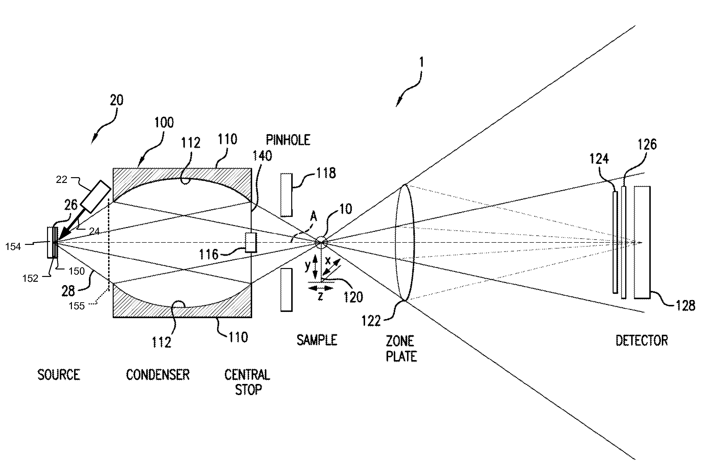
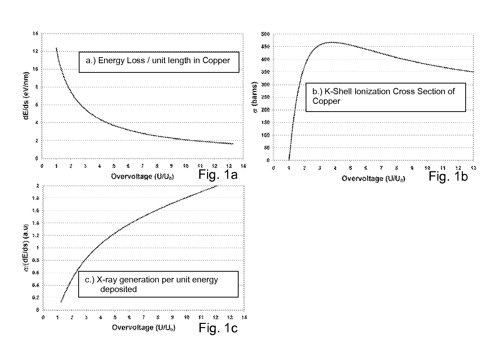
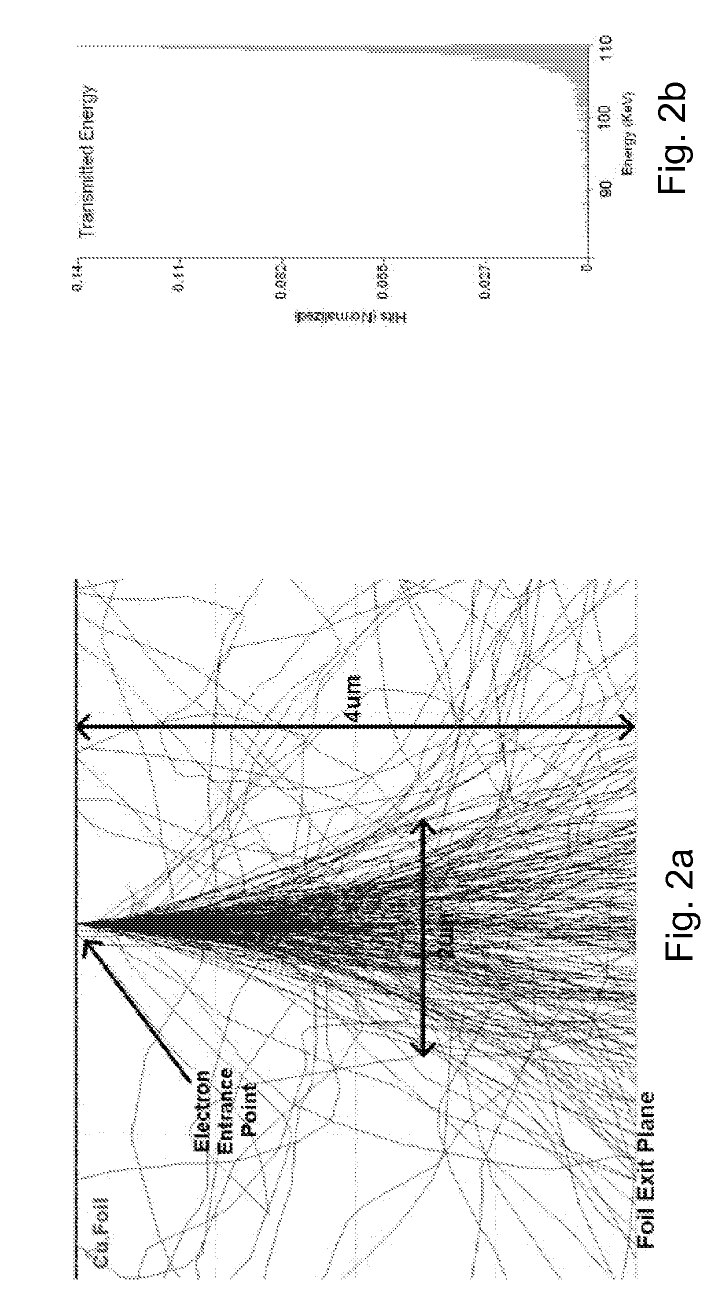
[0012]Embodiments of the present invention include a structured anode that has a thin top layer made of the desired target material and a thick bottom layer made of low atomic number and low density materials with good thermal properties. This structured target design allows for the use of efficient high energy electrons for the efficient generation of characteristic x-rays per unit energy deposited in the top layer and the use of the bottom layer as a thermal sink. This anode design can be applied to substantially increase the brightness of stationary, rotating anode or other electron bombardment-based sources where brightness is defined as number of x-rays per unit area and unit solid angle emitted by a source and is a key figure of merit for a source.
[0014]The present source can substantially improve the performance of many well established x-ray techniques, including x-ray microscopy, protein crystallography for determination of crystallographic structures of proteins and viruses, and small angle scattering for studying macromolecules in native solution.

Problems solved by technology

The key limiting factor for increasing brightness of this type of source is the melting of the anode target.
The accelerator and miniature synchrotron sources are currently expensive.
However, this method is limited to soft x-rays and not well suited for multi-kiloelectron Volts (KeV) x-rays that are desired for most for imaging.

Method used


Image

  • Structured anode X-ray source for X-ray microscopy
  • Structured anode X-ray source for X-ray microscopy
  • Structured anode X-ray source for X-ray microscopy

Examples


Embodiment Construction

[0025]Roentgen discovered in 1896 that when energetic electrons hit a target, x-rays are generated. This basic principle is still used in almost all commercial laboratory x-ray sources. The generated x-rays do not all have the same energy (and equivalently wavelength), but have a spectral distribution that contains a broad Bremsstrahlung (braking radiation) component and very narrow x-ray spectral lines known as the characteristic radiation. Many applications use the combined x-ray output e.g. medical radiography. However, applications that require strictly quasi-monochromatic (single wavelength) x-rays can only use the narrow x-ray lines of the characteristic radiation. For these applications, which include x-ray diffraction, small angle scattering, or x-ray microscopy using zone plates, the Bremsstrahlung component yields unwanted background and is suppressed by energy filtering or eliminated by monochromators. The following discussions only focus on characteristic x-ray radiation...


PUM


Abstract

An x-ray source comprises a structured anode that has a thin top layer made of the desired target material and a thick bottom layer made of low atomic number and low density materials with good thermal properties. In one example, the anode comprises a layer of copper with an optimal thickness deposited on a layer of beryllium or diamond substrate. This structured target design allows for the use of efficient high energy electrons for generation of characteristic x-rays per unit energy deposited in the top layer and the use of the bottom layer as a thermal sink. This anode design can be applied to substantially increase the brightness of stationary, rotating anode or other electron bombardment-based sources where brightness is defined as number of x-rays per unit area and unit solid angle emitted by a source and is a key figure of merit parameter for a source.

Description

RELATED APPLICATIONS[0001]This application claims the benefit under 35 U.S.C. 119(e) of U.S. Provisional Application No. 60 / 749,493, filed on Dec. 9, 2005 which is incorporated herein by reference in its entirety.BACKGROUND OF THE INVENTION[0002]X-ray microscopy is a technique that offers unique imaging through its combination of resolution, penetrating power, analytical sensitivity, compatibility with wet specimens, and ease of image interpretation. In the past, high resolution X-ray microscopy has been restricted to a few synchrotron radiation laboratories around the world. The emergence of laboratory source-based x-ray microscopes holds the opportunity to make this imaging modality much more widely available. Such laboratory-source x-ray microscopes, however, rely on the availability of high brightness x-ray sources for high performance.[0003]Resolution and throughput are two important parameters defining the performance of a microscope. The former defines smallest features that ...

Claims


Application Information

Patent Timeline
IPC IPC(8): G21K5/04
CPCG21K7/00H01J35/08H01J2235/088
Inventor YUN, WENBINGDUEWER, FREDERICK W.FESER, MICHAELTKACHUK, ANDREISESHADRI, SRIVATSAN
Owner CARL ZEISS X RAY MICROSCOPY
Learn More