Shielded electrical connector assembly

a shielding plate and electrical connector technology, applied in the direction of connection contact member materials, fixed connections, coupling devices, etc., can solve the problems of affecting the signal transmission, the shielding plate type cannot be applied to the surface mountable electrical connector, and the shielding plate is more complicated, etc., to achieve the effect of superior shielding characteristics

Inactive Publication Date: 2006-03-23
HON HAI PRECISION IND CO LTD
View PDF8 Cites 77 Cited by
  • Summary
  • Abstract
  • Description
  • Claims
  • Application Information

AI Technical Summary

Benefits of technology

[0007] An object of the present invention is to provide an ele...

Problems solved by technology

However, the contacts are not absolutely shielded by the shell, therefore, under high frequency operations, electromagnetic interference (EMI) may cause adverse influence to the signal transmission.
However, since contacts and shielding plates of the shielded connector are inserted into holes of a circuit board and soldered therein in the direction vertical to the surface of the circuit board, but this type of...

Method used


Image

  • Shielded electrical connector assembly
  • Shielded electrical connector assembly
  • Shielded electrical connector assembly

Examples


Embodiment Construction

[0019] Reference will now be made to the drawing figures to describe the preferred embodiment of the present invention in detail.

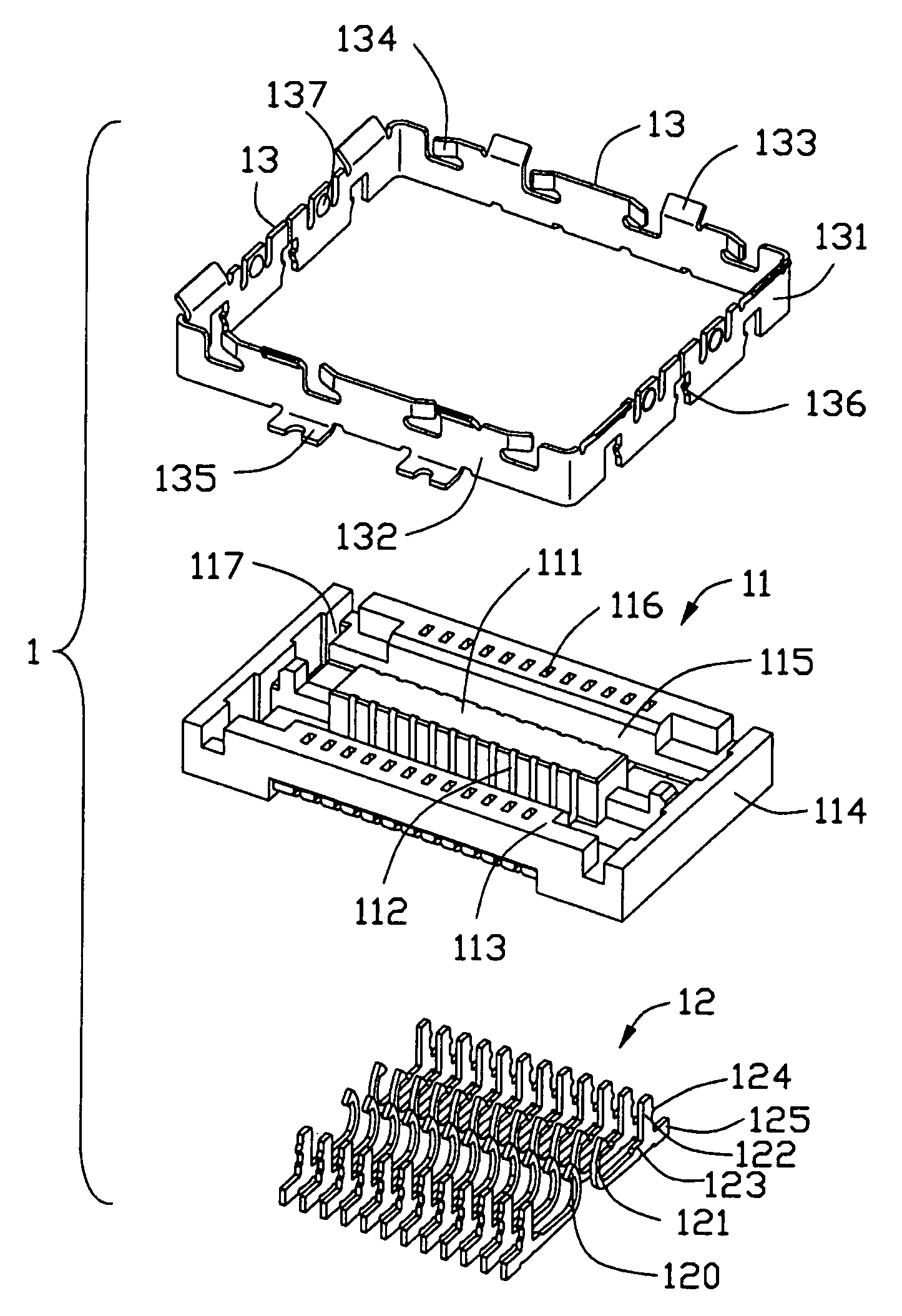
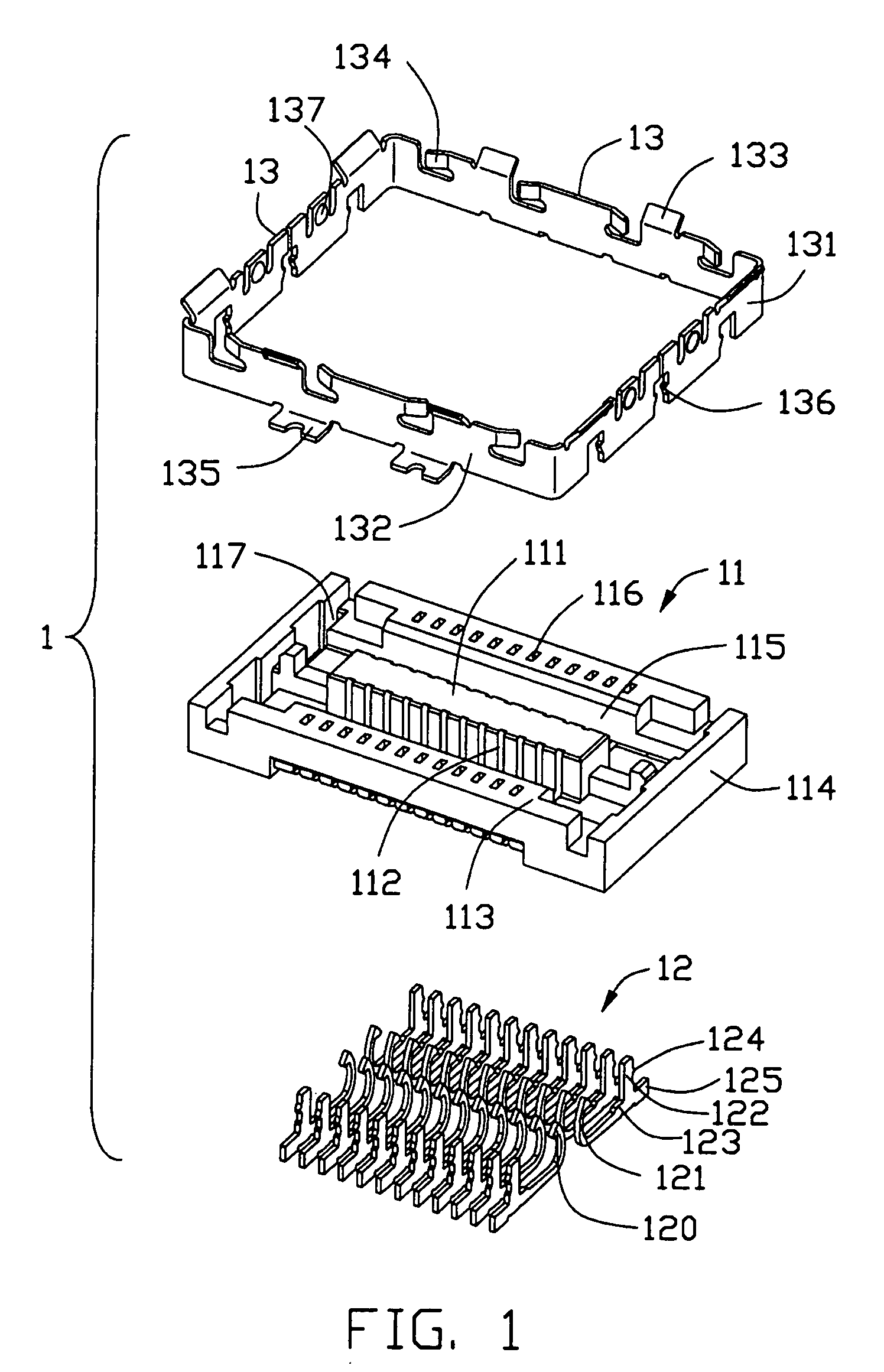
[0020] Referring to FIGS. 1, 4 and 8, an electrical connector assembly 100 in accordance with the present invention comprises a receptacle connector 1 and a mating plug connector 2, the receptacle connector 1 is mounted on one circuit board (not shown), and the plug connector 2 is mounted on the other circuit board (not shown). The receptacle connector 1 and the plug connector 2 are mated together to establish a connection between two circuit boards.

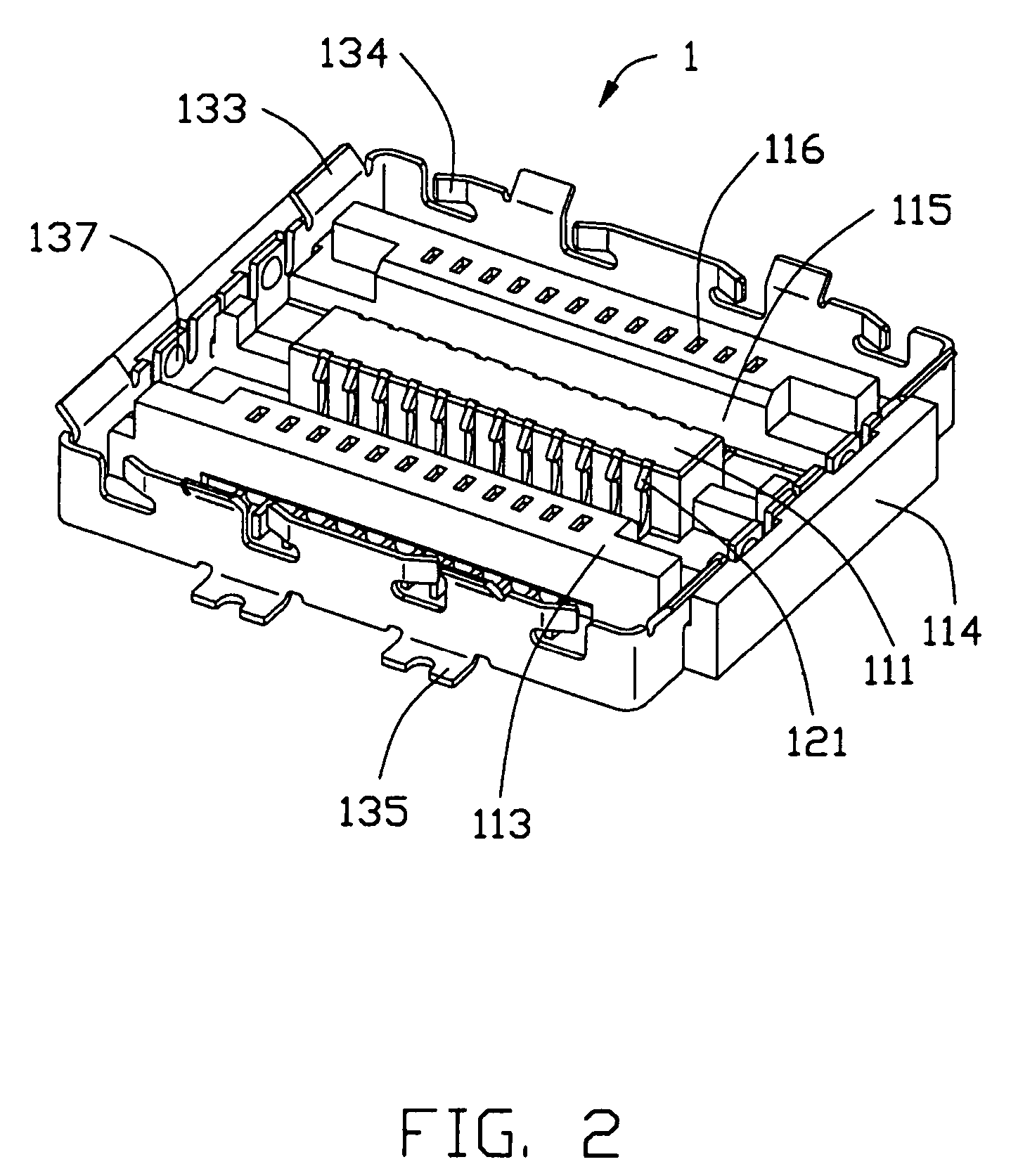
[0021] Referring to FIGS. 1-3, the receptacle connector 1 includes an insulative housing 11 and a plurality of conductive contacts 12 arranged at regular intervals along the length of the housing 11, the contacts 12 are arranged in two arrays and fixed to the housing 11. The housing 11 has a rectangular central portion 111, a pair of side walls 113, and a pair of opposite end walls 114 surrounding the central...


PUM


Abstract

An electrical connector for mounting on a circuit board includes an insulative housing (11) having a pair of side walls (113), a pair of end walls (114) and defining a mating opening (115), and a mounting face and a number of contact receiving slots (112); a plurality of contacts (12) received in the contact receiving slots and each having a soldering portion (125) extending along the mounting face for surface mounting on the circuit board; a pair of shielding plates (13) each having a main portion (132) located outside tail ends of the soldering portion, a bent portion (131) bent from opposite ends of the main potion and attached to the end walls and a grounding pad (135) extending along the mounting face for surface mounting on the circuit board.

Description

BACKGROUND OF THE INVENTION [0001] 1. Field of the Invention [0002] The present invention relates to an electrical connector assembly, and more particularly to a shielded electrical connector assembly for connecting two circuit boards. [0003] 2. Description of Related Art [0004] A variety of electrical connector assemblies have been used to establish electrical connection between two separate circuit boards. The electrical connector assembly generally includes a plug connector mateable with a receptacle connector. [0005] U.S. Pat. No. 5,697,799 discloses a receptacle connector mating with a plug connector comprising a housing, a plurality of contacts mounted in the housing and a shell surrounding the housing. Solder tails of outer rows of contacts extend outwardly of side walls of the housing and side walls of the shell for soldering to a circuit board. However, the contacts are not absolutely shielded by the shell, therefore, under high frequency operations, electromagnetic interfe...

Claims


Application Information

Patent Timeline
IPC IPC(8): H01R13/648H01R12/16
CPCH01R12/57H01R12/716H01R23/6873H01R13/658
Inventor CHEN, MING-CHING
Owner HON HAI PRECISION IND CO LTD
Why Eureka
Try Eureka