
Flush toilet and deodorizing method of the same

Inactive Publication Date: 2006-03-30
SANYO ELECTRIC CO LTD
View PDF3 Cites 29 Cited by
  • Summary
  • Abstract
  • Description
  • Claims
  • Application Information

AI Technical Summary

Benefits of technology

[0007] It is an object of the present invention to provide a flush toilet equipped with a deodorizing apparatus and a deodorizing method of the flush toilet which effectively remove a source of an offensive odor in the flush toilet and which can decompose the odor and also clean and sterilize a toilet bowl.
[0018] According to the present invention, a source of an offensive odor in a flush toilet can be removed, and the odor can be decomposed. Moreover, according to the present invention, the bowl of the flush toilet can be cleaned and sterilized.

Problems solved by technology

However, this deodorizing apparatus has problems that it is necessary to provide the drain pipe in an intermediate part between a discharge part of the bowl and the sewage and it is not easy to install the drain pipe in an existing bowl, and that because the water containing member contains water, a pressure loss is caused by the water containing member when the offensive odor components are sucked in.
However, such a method of supplying the sterile water to the filter has a problem that the sterile water might deteriorate the filter, and that the wet filter causes a great pressure loss to increase load in the suction of the offensive odor components.

Method used


Image

  • Flush toilet and deodorizing method of the same
  • Flush toilet and deodorizing method of the same
  • Flush toilet and deodorizing method of the same

Examples


embodiment 1

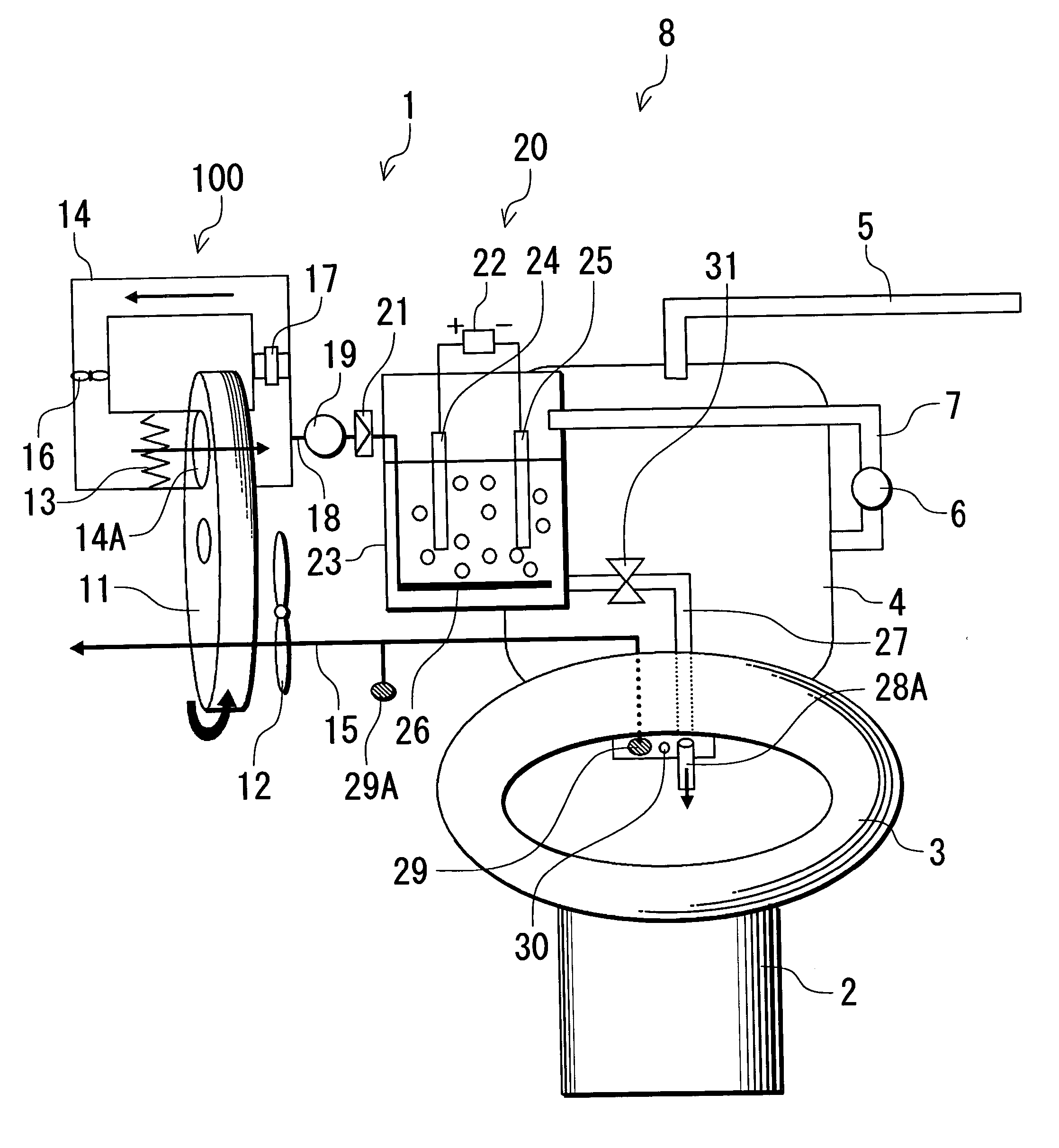
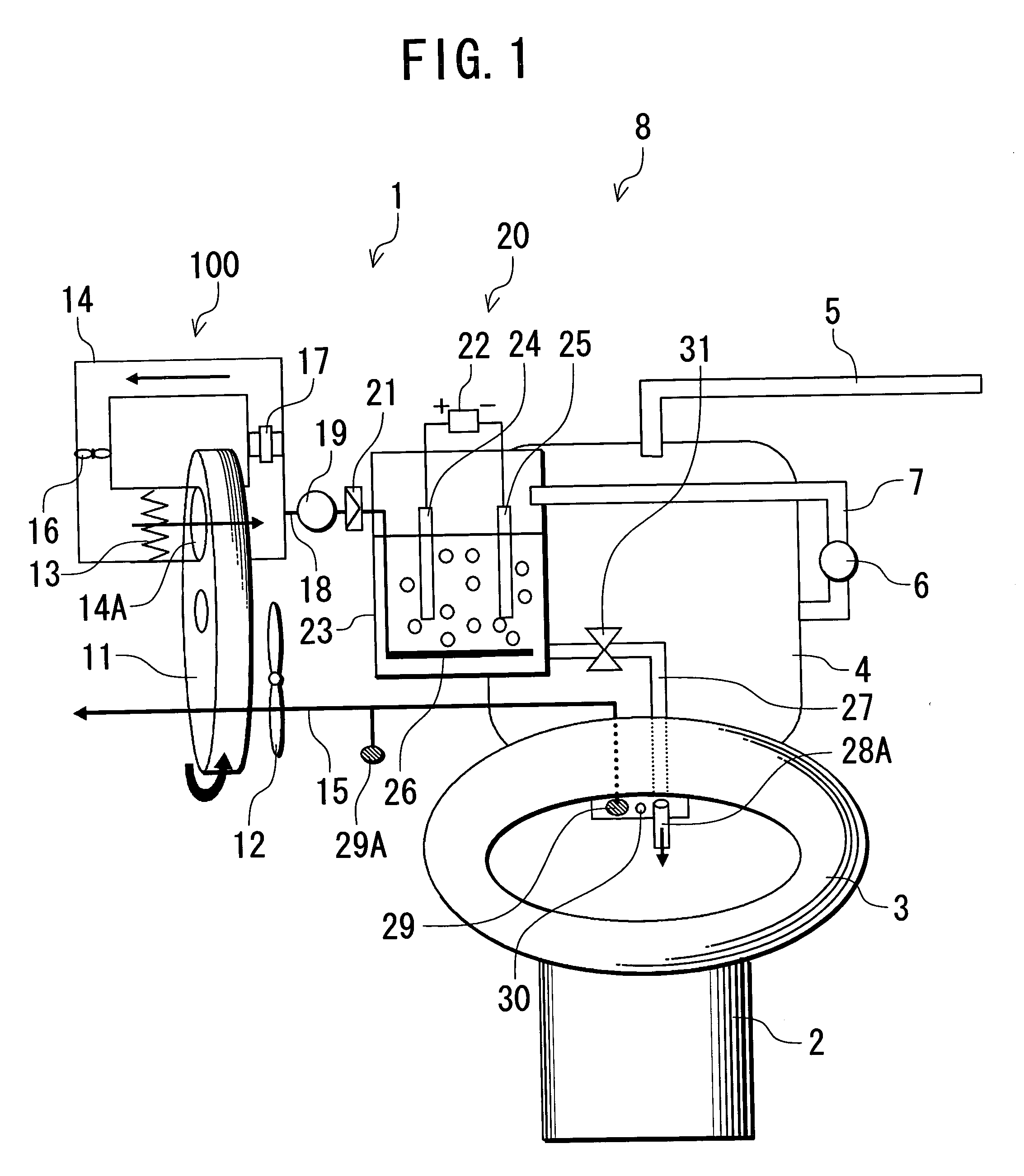
[0030] One embodiment of the present invention will be described in detail with reference to the drawings. FIG. 1 shows a schematic configuration diagram of a flush toilet 8 equipped with a deodorizing apparatus 1 as the one embodiment of the present invention.

[0031] In the present embodiment, the flush toilet 8 includes the deodorizing apparatus 1 comprising an odor adsorption device 100 and an electrolysis device 20; a bowl 2; a seat 3; a water storage tank 4 to flush the bowl 2; a water supply pipe 5 coupled to an unshown water pipe to supply water to the water storage tank 4; and a hot water cleaning device 30 comprising an unshown hot water tank and the like.

[0032] The odor adsorption device 100 comprises a disk-shaped adsorption member 11 rotated at a predetermined speed; an air intake fan 12 which takes in an odor in the bowl 2 and an odor in a toilet room from an odor suction port 29 and an odor suction port 29A via an odor flow path 15 to pass air containing the odors to ...

embodiment 2

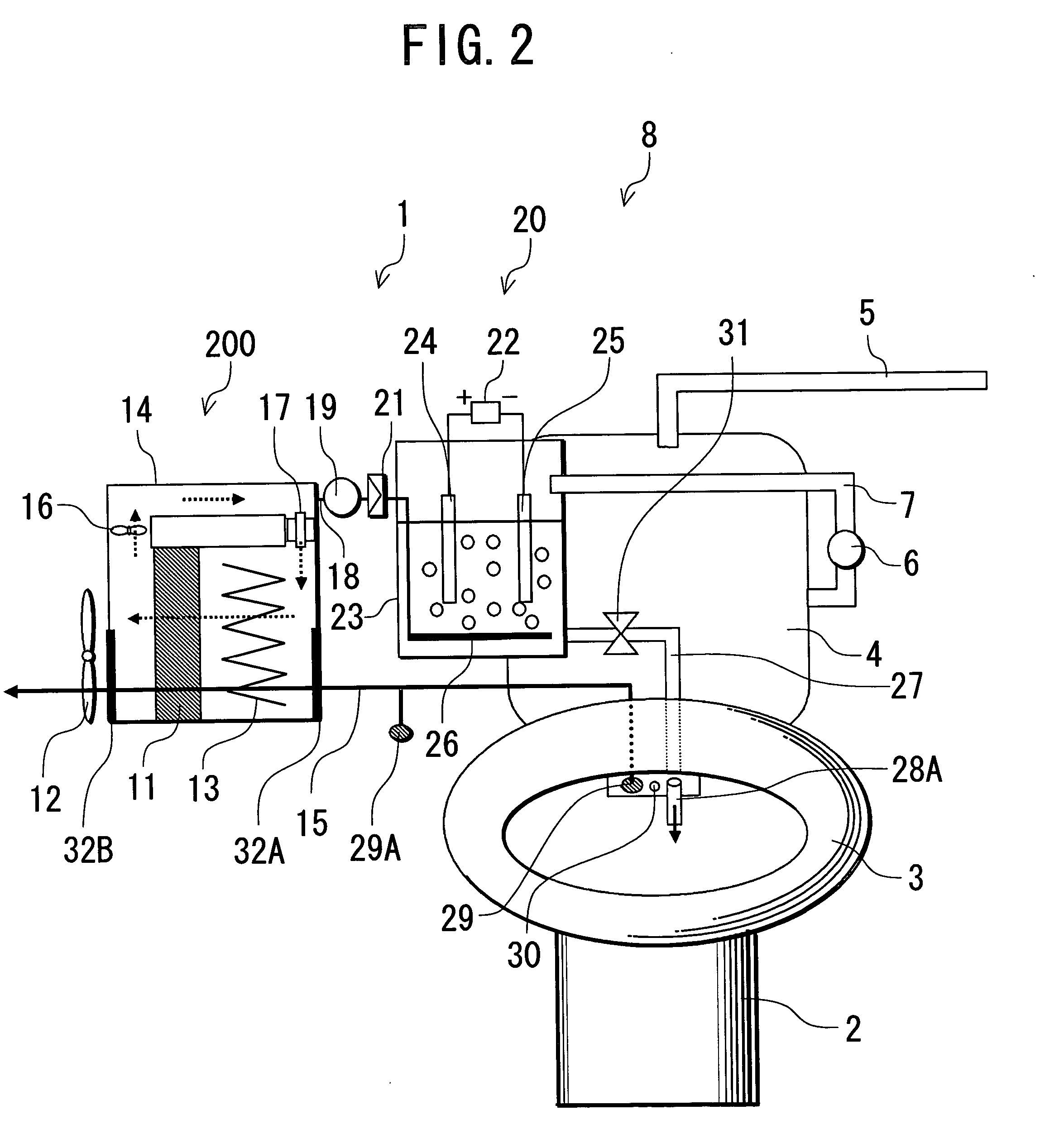
[0077]FIG. 2 shows a schematic configuration diagram of a flush toilet 8 equipped with a deodorizing apparatus 1 in a second embodiment of the present invention. It is to be noted that those assigned with the same numbers in FIG. 2 as those in Embodiment 1 have the same or similar functions and effects. In this case, a configuration similar to that in Embodiment 1 is provided except that an adsorption member 11 is provided in a circulation path 14 without a rotation mechanism such as the motor described above, that an odor flow path 15 communicates with a circulation path 14, and that lids 32A, 32B are provided at a portion where the odor flow path 15 is connected to the circulation path 14. It is to be noted that the adsorption member 11 in the present embodiment does not have the rotation mechanism, but when capacity of the adsorption member 11 to adsorb and release odor components is to be increased, the rotary adsorption member 11 similar to that in Embodiment 1 can be provided ...

embodiment 3

[0081] Next, FIGS. 3 and 4 show schematic configuration diagrams of a flush toilet 8 equipped with a deodorizing apparatus 1 in a third embodiment of the present invention. It is to be noted that those assigned with the same numbers in FIGS. 3 and 4 as those in the above embodiments have the same or similar functions and effects. In this case, a configuration similar to those in the above embodiments is provided except that an electrolytic water flow path 27 branches into outlet ports 28B and 28C in addition to an outlet port 28A at a downstream portion of a valve 31.

[0082] Thus, in the flush toilet 8 equipped with the deodorizing apparatus 1 in the present embodiment, electrolytic water from an electrolytic cell 23 is flown into a bowl 2 in three directions by the outlet ports 28A, 28B and 28C, so that cleaning and the like inside the bowl 2 can be implemented more uniformly and in a wider range than in a case where the cleaning and the like inside the bowl 2 are implemented with ...


PUM


Abstract

An object of the present invention is to provide a flush toilet and a deodorizing method of the flush toilet which effectively remove a source of an offensive odor in the toilet and which can decompose the odor and also clean and sterilize a toilet bowl. A flush toilet 8 is equipped with a deodorizing apparatus 1, and the deodorizing apparatus 1 comprises: an electrolytic cell fitted with at least a pair of electrodes and storing tap water; odor suction means for sucking in an odor in the toilet; odor supply means for supplying the odor sucked in by the odor suction means into the electrolytic cell, odor adsorption means capable of adsorbing and releasing the odor; and odor supply means for supplying the odor released from the odor adsorption means to the electrolytic cell.

Description

BACKGROUND OF THE INVENTION [0001] 1. Field of the Invention [0002] The present invention relates to a flush toilet equipped with a deodorizing apparatus, and more particularly, it relates to a flush toilet and a deodorizing method of the flush toilet capable of cleaning and sterilizing a toilet bowl. [0003] 2. Description of the Related Art [0004] To remove an odor during use of a flush toilet, it may be insufficient to merely flush it away after use, and various deodorizing apparatuses have heretofore been proposed to deodorize the flush toilet. [0005] Japanese Patent Publication Laid-open No. 3-286052 discloses a deodorizing apparatus wherein after an odor in a toilet bowl is sucked in by an operation of a ventilator, the odor is blown to a water containing member supplied with water in order to dissolve an offensive odor components in the water in the water containing member, and then it is discharged to sewage through drain pipes. However, this deodorizing apparatus has problem...

Claims


Application Information

Patent Timeline
IPC IPC(8): E03D9/04
CPCE03D9/05
Inventor YAMAMOTO, TETSUYARAKUMA, TSUYOSHITAKAOKA, DAIZO
Owner SANYO ELECTRIC CO LTD
Learn More