Diaphragm valve

a technology of diaphragm valve and valve body, which is applied in the field of diaphragm valves, can solve the problems of limited space available for such valves, reduce the service life of robots, and be particularly problematic, and achieve the effects of reducing weight, improving service life, and increasing the wall thickness of the valve body

Inactive Publication Date: 2006-03-30
NORDSON CORP
View PDF24 Cites 29 Cited by
  • Summary
  • Abstract
  • Description
  • Claims
  • Application Information

AI Technical Summary

Benefits of technology

[0006] Supplying pressurized fluid, such as a pressurized gas, through a passageway formed in the piston stem for the purposes of operating the valve, i.e. changing the valve position, allows the valve to be smaller and lighter than conventional valves having side mounted air fittings. This is because the outside diameter of conventional valves having side mounted air fittings must be larger than the outside diameter of the valve of the present invention, to increase the wall thickness of the valve body as required to accommodate an internally threaded port to mate with a conventional externally threaded fluid coupling that is part of an air supply system.
[0007] Additional weight reduction is achieved when the couplings that mate to conventional valves and to the valve of the present invention are considered. For instance, with conventional valves utilizing side mounted air supply, a 90° elbow is typically threaded into an internally threaded port on the side of the valve because such an elbow fitting can accommodate the main air supply line to be disposed generally parallel to the centerline of the valve. Such an elbow is heavier and bulkier than the conventional fluid coupling that can be used to mate with the passageway formed in the piston stem of the valve of the present invention. The reduction in weight and size of the valve of the present invention, as compared to conventional valves, results in various advantages. For example, when the valve of the present invention is mounted on a robot arm, the reduced valve weight enhances the ability of the robot arm to rotate about multiple axes and to move from one position to another within the time required in a production line environment. Furthermore, the reduced valve weight can increase the service life of the robot.
[0008] Also, when mounted on a robot arm, the reduced size of the valve enhances the ability of other devices to access a work piece, which receives a liquid dispensed from the valve of the present invention.

Problems solved by technology

This can be particularly problematic in applications where size and weight are important design considerations.
For instance, with valves mounted to a robotic arm, that pivots about XYZ axes and dispenses fluid onto a work piece, limited space may be available for such valves when the complex movement of the robotic arm and valve are considered together with the need for other devices to access the work piece.
The increased valve mass also increases operational loads on the robot arm that can reduce the service life of the robot.

Method used


Image

  • Diaphragm valve
  • Diaphragm valve
  • Diaphragm valve

Examples


Embodiment Construction

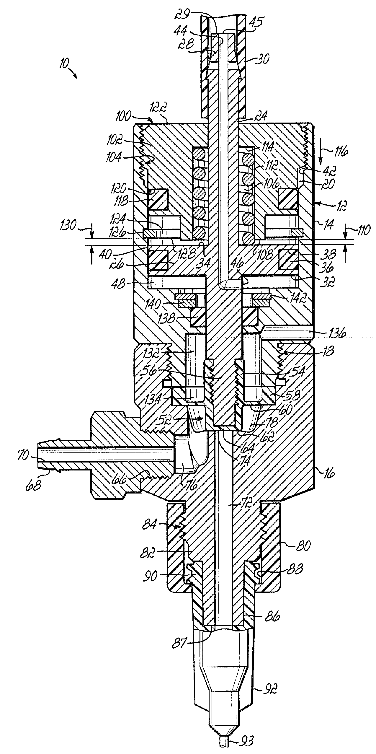
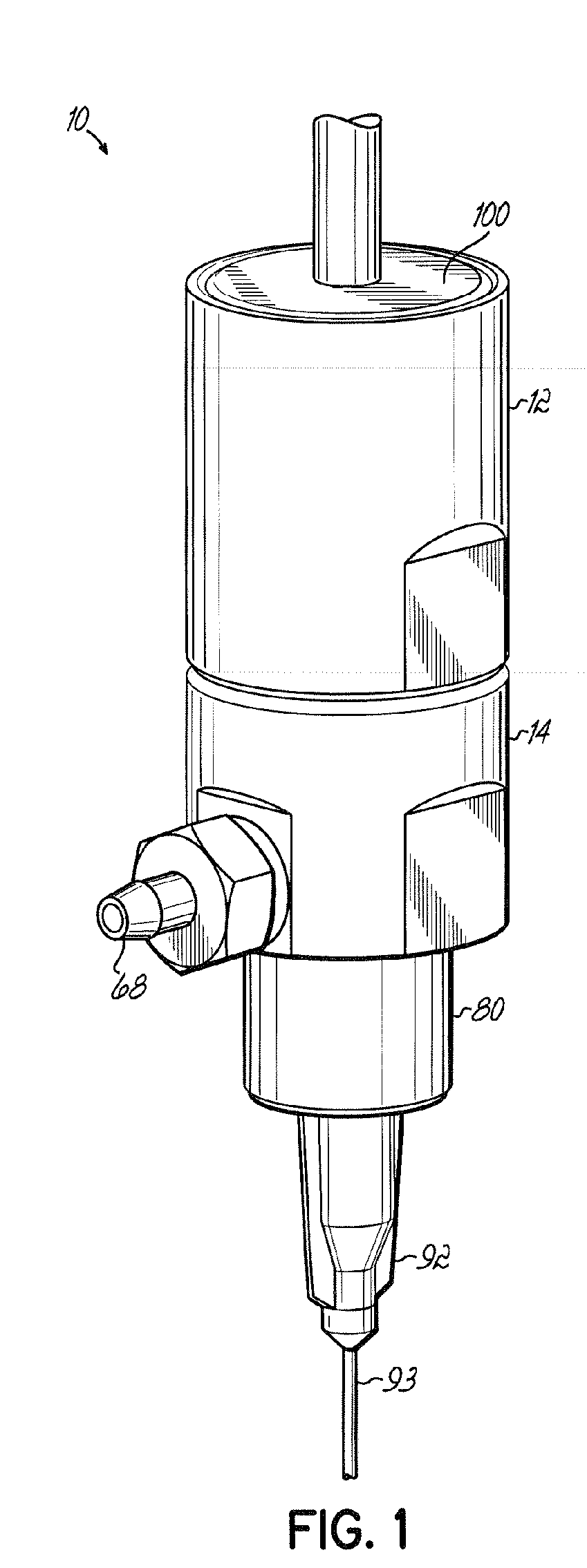
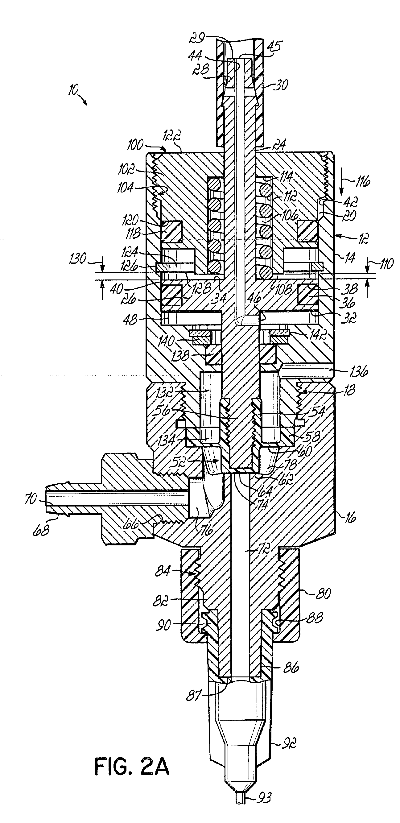
[0014] Referring now to the drawings, FIG. 1 is a perspective view illustrating a valve 10 according to one embodiment of the present invention. Valve 10 includes a body, indicated at 12, with body 12 including a first body portion 14 and a second body portion 16 which are threadably engaged with one another at 18. Body 12 includes an interior cavity 20, which is formed in the first body portion 14. Valve 10 further includes an axially extending valve stem 24 mounted for axial movement between open and closed positions, corresponding to open and closed positions of valve 10, within valve body 12. A piston element 26 is carried by valve stem 24 and is positioned within the interior cavity 20. In the illustrative embodiment, piston element 26 is a disk. In one embodiment, valve body 12, valve stem 24 and piston element 26 are made of type 303 stainless steel. However, other suitable materials can be utilized. For instance, alternate materials for valve body 12 include type 316 stainle...


PUM


Abstract

A valve is provided for use in a fluid dispensing system. The valve includes a valve body having an interior cavity and a valve stem mounted for axial movement between open and closed positions within the valve body. The valve stem includes an actuation air passageway having an air inlet and an air outlet, with the air inlet being adapted to be coupled to a source of pressurized actuation air. The air outlet communicates with said interior cavity. The valve also includes a piston element carried by the valve stem and positioned within the interior cavity. The valve further includes a liquid inlet, a liquid outlet, and a valve seat positioned between the liquid inlet and the liquid outlet, whereby the valve stem is movable from the closed position to the open position relative to the valve seat when pressurized actuation air is introduced into the interior cavity through the actuation air passageway and acts against the piston element.

Description

CROSS REFERENCES [0001] This application claims the priority benefit of U.S. Provisional Patent Application Ser. No. 60 / 613,692, “Miniature Diaphragm Valve”, filed Sep. 28, 2004, which is expressly incorporated by referenced herein in its entirety.FIELD OF THE INVENTION [0002] This invention relates to valves and, more particularly, to diaphragm valves. BACKGROUND OF THE INVENTION [0003] Diaphragm valves, including pneumatically controlled diaphragm valves, are known in the art. Typically valves of this type use air pressure to raise a piston against the force of a spring to change the valve from a closed position to an open position to allow fluid to be dispensed from the valve. This air pressure is typically provided through a fitting connected to the side of the valve below the piston. While valves of this type have been advantageously utilized in the fluid dispensing industry, the side mounted air supply adds to the valve weight and to the overall size of the valve. This is beca...

Claims


Application Information

Patent Timeline
Patent Type & Authority Applications(United States)
IPC IPC(8): F16K31/143
CPCF16K31/1221F16K41/103F16K31/1226B05B1/306B05B13/0431F16K7/17F16K31/126
Inventor STRONG, WARREN N.
Owner NORDSON CORP
Why Eureka
Try Eureka