Controlled dispersion multi-phase nozzle and method of making the same

a multi-phase, nozzle technology, applied in the direction of instruments, liquid/fluent solid measurement, volume/mass flow by differential pressure, etc., can solve the problem that the nozzle does not control the dispersion angle of the nozzl

Active Publication Date: 2006-03-30
CALDERA ENG
View PDF31 Cites 27 Cited by
  • Summary
  • Abstract
  • Description
  • Claims
  • Application Information

AI Technical Summary

Benefits of technology

[0026] It is desirable to provide a nozzle having a choke device that can provide an optimal flow pattern at th

Problems solved by technology

Generally, these prior nozzles do not

Method used


Image

  • Controlled dispersion multi-phase nozzle and method of making the same
  • Controlled dispersion multi-phase nozzle and method of making the same
  • Controlled dispersion multi-phase nozzle and method of making the same

Examples


Embodiment Construction

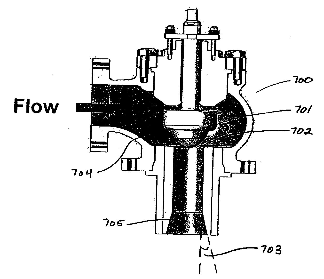
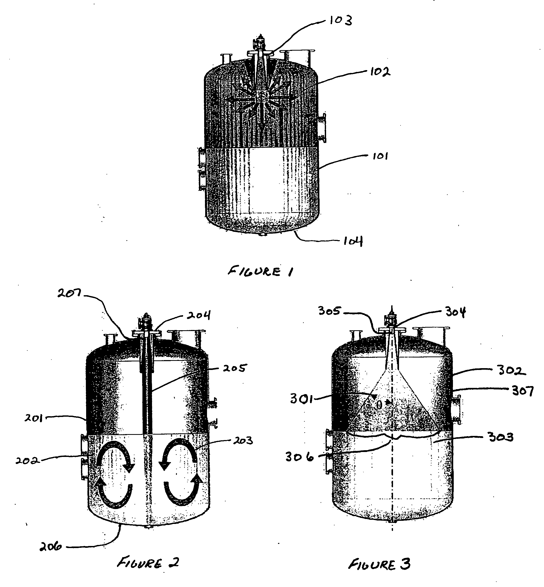
[0047] This invention is a controlled dispersion multiple phase nozzle for use in controlling phase change during pressure letdown. Phase change during pressure letdown has the potential to release significant amounts of energy. For example, in autoclave mining operations each state of pressure letdown in a three-stage system may require the dissipation of one to two megawatts of power. Because slurry is acidic and abrasive, the materials required to control these systems can be very expensive. Turbines and other techniques to productively use the energy release have not thus far been demonstrated to be feasible. This invention addresses the significant challenge of dissipation of this energy without excessive wear and tear on relatively expensive equipment.

[0048] The control of the dissipation of energy during pressure letdown accomplished in this invention has been developed with use of a model of the letdown process. This model has been used to predict the pressure, velocity and...


PUM


Abstract

A nozzle design and method for designing such a nozzle being adapted for three phase slurry flow from the choke into the flash tank during pressure let-down in autoclave mining operations that uses a selection of the expansion ratio in the choke to select a nozzle dispersion angle to select a spread of the flow over the slurry pool in the flash tank, to generally maximize the use of the pool for energy dissipation without causing undo wear and tear on the tank walls.

Description

CROSS REFERENCE TO RELATED APPLICATIONS [0001] This application claims the benefit of prior, co-pending, commonly owned U.S. Provisional Patent Application Ser. No. 60 / 570,925, entitled Controlled Dispersion Multi-Phase Nozzle and Method of making the Same, filed on May 13, 2004 and naming as inventors Stephen R. Chipman, Michael R. Luque, Herman Pieterse, Jeffrey C. Robison and Craig C. Smith.BACKGROUND OF INVENTION [0002] 1. Field of the Invention [0003] This invention relates to a nozzle for the control of the pattern of a flashing multi-phase flow at the outlet of a pressure let-down valve. More specifically, this invention relates to a nozzle with a choke that provides an optimal flow pattern at exit, by controlling the nozzle dispersion angle to match the elements in the receiving tank. [0004] 2. Description of Related Art [0005] A variety of nozzles for use in pressure let-down valves have been proposed. Generally, these prior nozzles do not control the nozzle dispersion angl...

Claims


Application Information

Patent Timeline
IPC IPC(8): F16K47/16
CPCF16K47/16
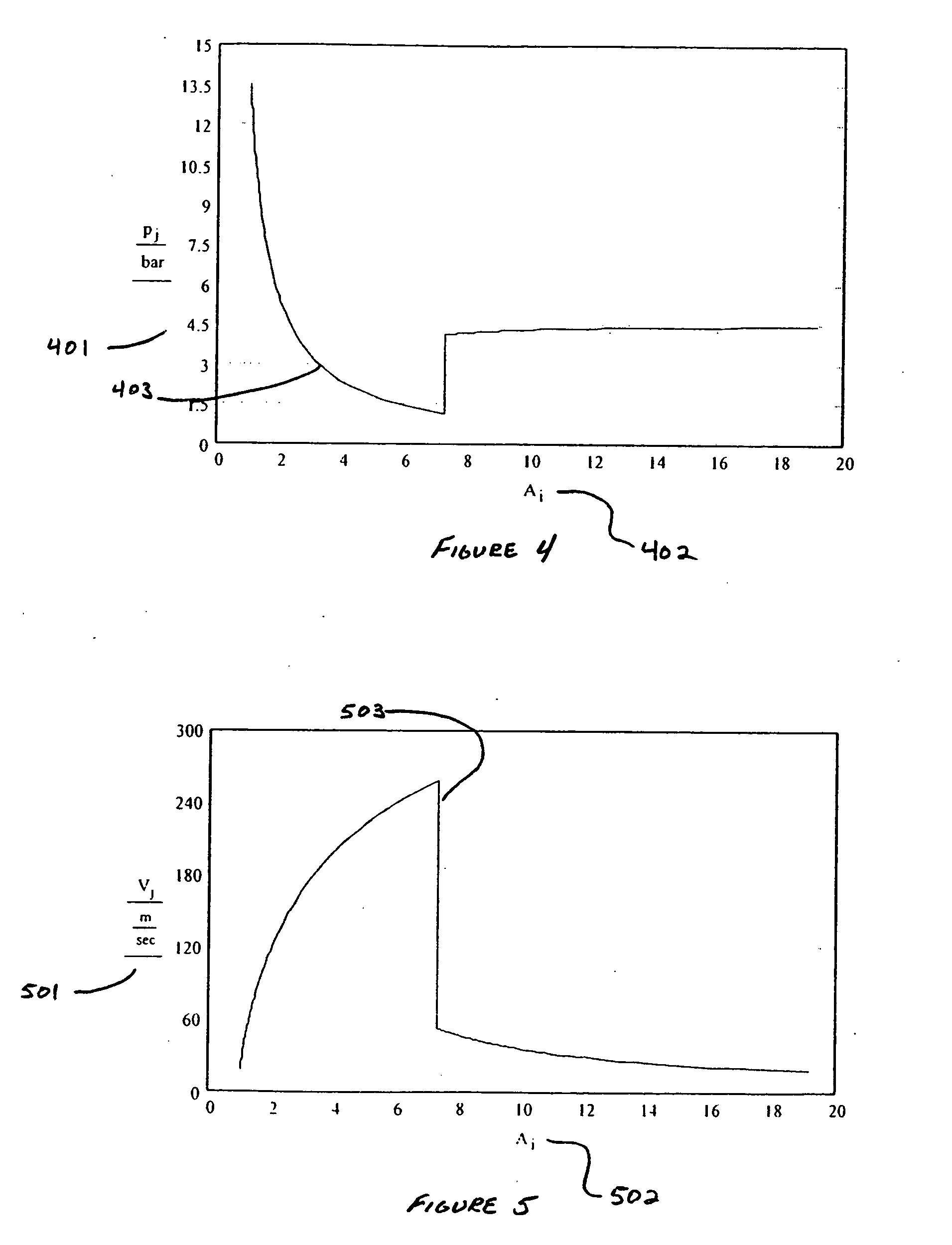
Inventor CHIPMAN, STEPHEN R.LUQUE, MICHAEL R.PIETERSE, HERMANROBISON, JEFFREY C.SMITH, CRAIG C.
Owner CALDERA ENG
Why Eureka
Try Eureka