Method and apparatus for producing dope and solution casting method

a technology of liquid crystal display and solution casting, which is applied in the direction of emulsification, transportation and packaging, and other domestic objects, can solve the problems of poor influence of mixing unevenness of additives on display, inability to perform stirring ecciciently, and inability to achieve effective stirring, improve the view angle dependence of liquid crystal display, and reduce the size of the production process

Inactive Publication Date: 2006-03-30
FUJIFILM CORP +1
View PDF5 Cites 15 Cited by
  • Summary
  • Abstract
  • Description
  • Claims
  • Application Information

AI Technical Summary

Benefits of technology

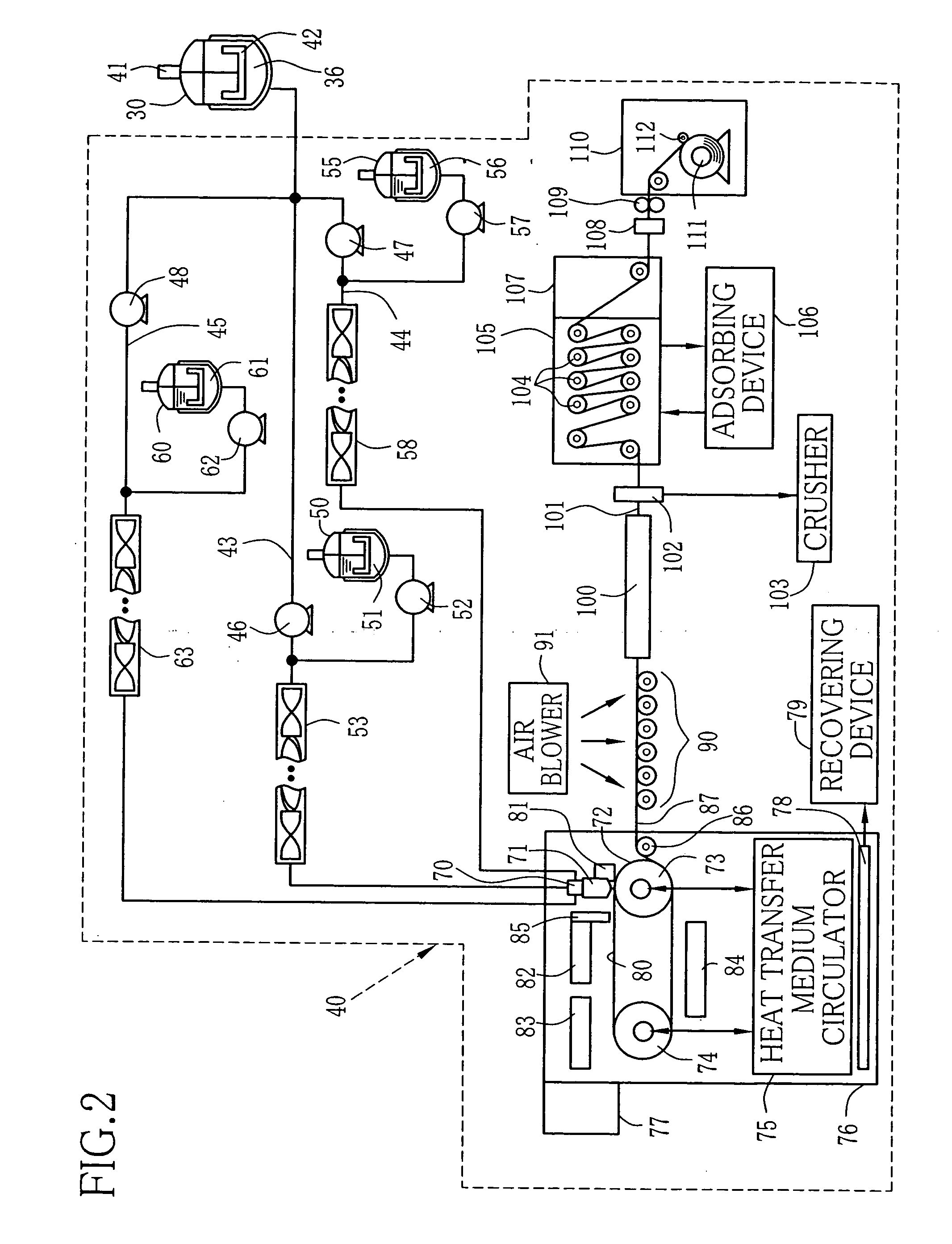
[0020] The film produced by the solution casting method of the present invention may construct a protective film for a polarizing filter and a film base of a photo film. Further, the film may be used as an optical compensation film for improving a view angle dependence of the liquid crystal display for a TV monitor. Especially, the film is effectively used for doubling as protective film for the polarizing filter. Therefore, the film can not be used for only TN mode, but also IPS mode, OCB mode, VA mode and the like. Further, the polarizing filter may be constructed with use of the protective film for the polarizing filter.
[0021] According to the present invention, the additive is added through the slit-like orifice extending in the diameter direction of the tube in which the polymer solution flows. Therefore, the mixing and stirring of a mixture of the additive and the polymer solution is efficiently made in the inline mixer. Consequently, a number of the elements in the inline mixer may be smaller. Thus the size of the production process becomes smaller and the cost becomes lower.
[0022] Further, the mixing and stirring of the additive and the polymer solution is efficiently made, and the obtained dope is uniform. Therefore, when the dope is used in the solution casting method, the produced film is used for the protective film for the polarizer, the optical compensation film and the film base. Thus the product has high quality.

Problems solved by technology

In such an extended definition television, even slight mixing unevenness of additives has large bad influences on displaying.
If the stirring is not enough, the quality of the production becomes lower.
However, in the methods of the prior arts, the stirring cannot be performed ecciciently.
Namely, since the additive is added from a cylindrical addition nozzle disposed nearly in a middle of a pipe in which the polymer solution is fed, it takes long time that the additives spread from the center to an inner wall of the pipe.
Therefore, in order to perform the stirring enough, the static mixer to be used has many elements, which causes a large processing system and high cost.

Method used


Image

  • Method and apparatus for producing dope and solution casting method
  • Method and apparatus for producing dope and solution casting method
  • Method and apparatus for producing dope and solution casting method

Examples


example 1 (

EX. 1)

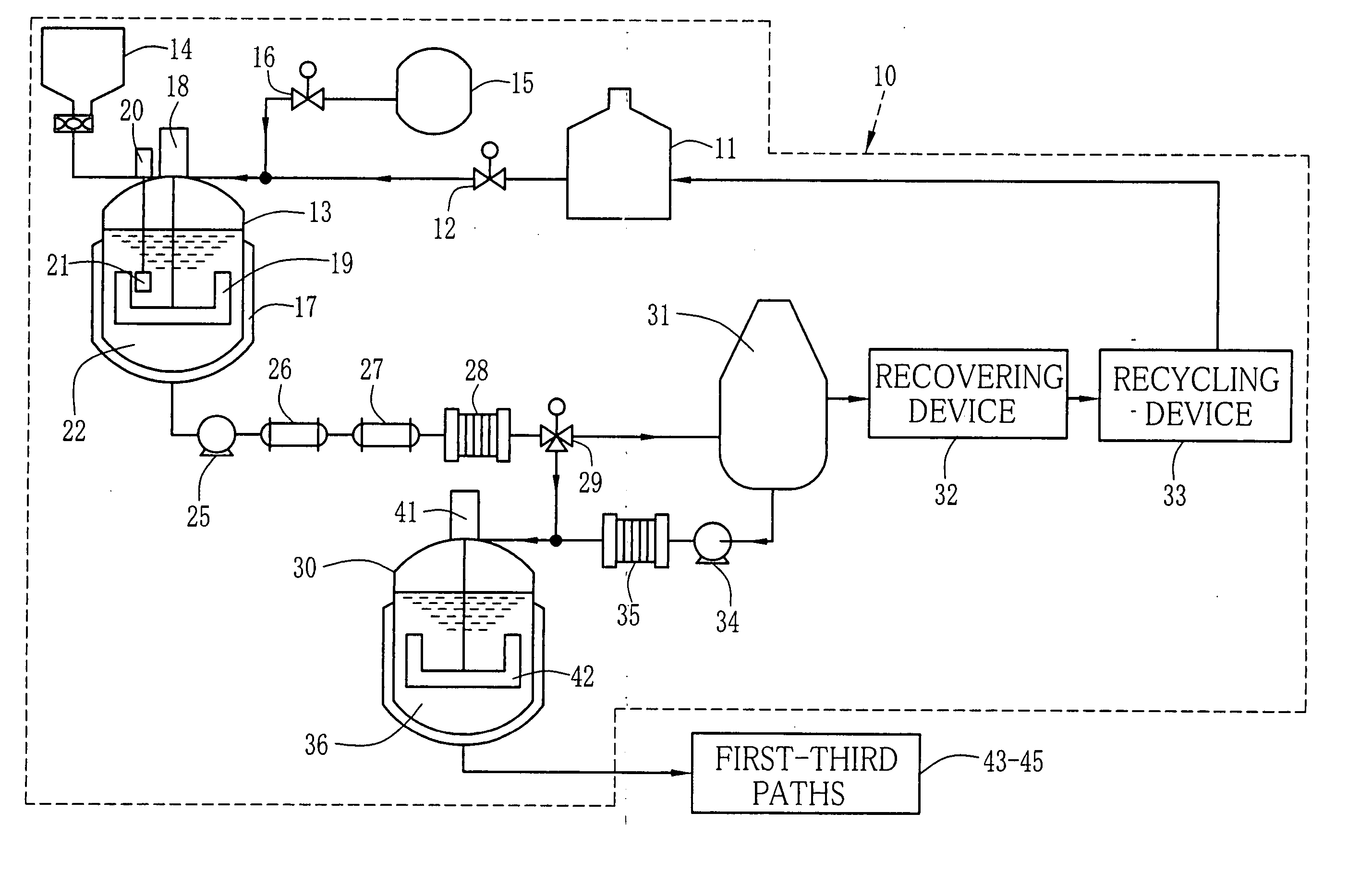
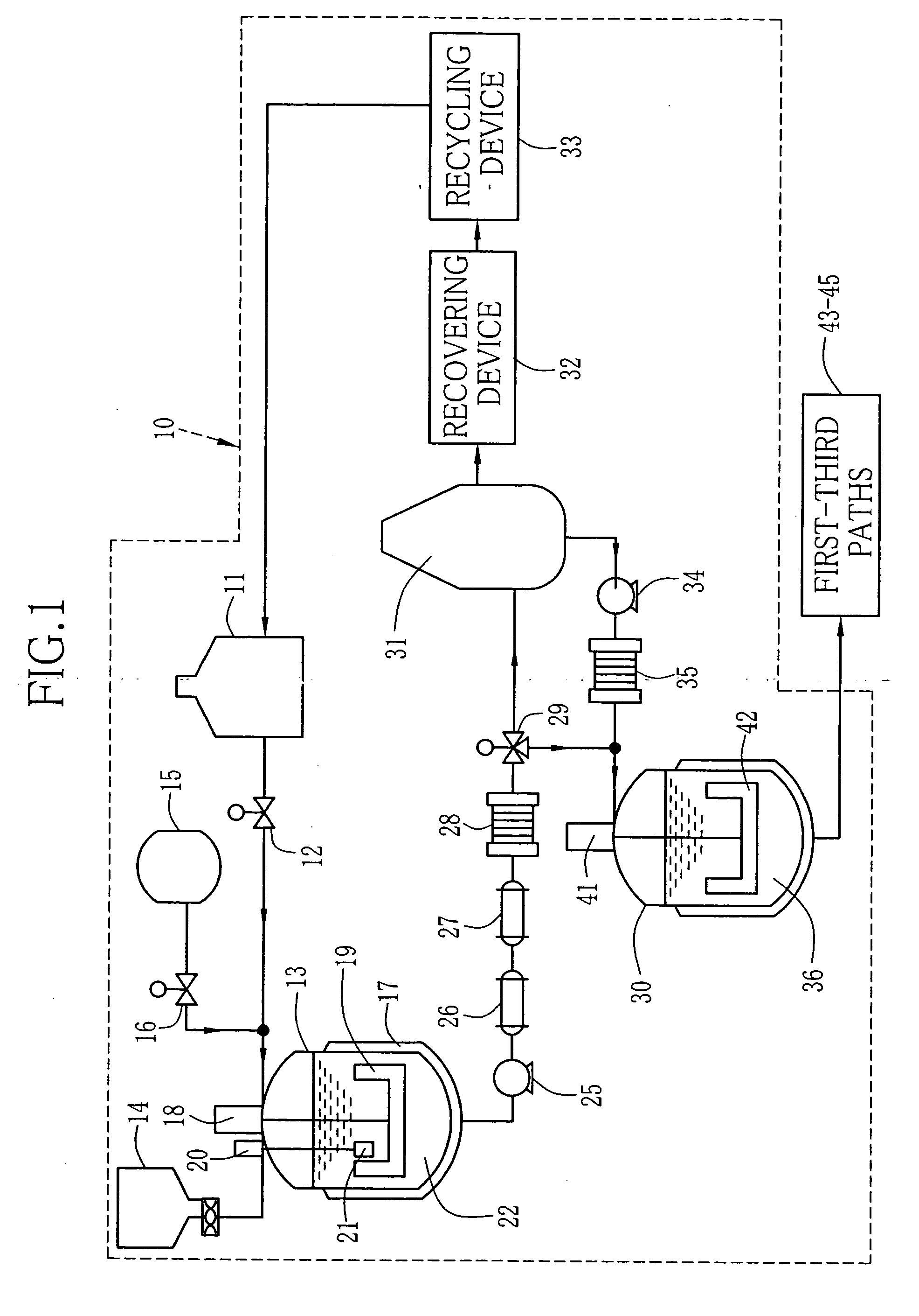
[0164] The flow velocity ratio V1 / V2 between the flow velocity V1 of the additive and the flow velocity V2 of the polymer solution was 3. The viscosity N2 of the polymer solution was 20000 cp, and the viscosity N1 of the additive was 0.5 cp. The addition ratio of the additive, as ratio of the flow velocity, was 20%. The shearing rate V3 of the polymer solution was 1.3 (1 / s), and Reynolds Number Re was 5. The distance D between the slit and the static mixer was 10 mm. An element number of the static mixer was 42. According to the dope produced under the conditions, the mixing condition was good and the coloring unevenness wasn't bserved. Therefore the estimation was A (excellent).

examples 2-5 (ex.2-5)

EXAMPLES 2-5 (EX. 2-5)

[0165] In Examples 2-5, the flow velocity ratio V1 / V2 was changed. In Example 2, the flow velocity ratio V1 / V2 was 0.9. In Example 3, the flow velocity ratio V1 / V2 was 1. In Example 4, the flow velocity ratio V1 / V2 was 5. In Example 5, the flow velocity ratio V1 / V2 was 5.5. Other conditions were the same as in Example 1. As the results, according to the dope in Example 2, the mixing condition was good and the coloring unevenness wasn't remarkable. Therefore the estimation was B (good). Further, according to the dopes in Examples 3 & 4, the mixing condition was good and the coloring unevenness wasn't observed. Therefore the estimation was A (excellent). According to the dope in Examples 5, the mixing condition was not so good and the coloring unevenness was sometimes observed. Therefore the estimation was C (usable).

examples 6-8 (ex.6-8)

EXAMPLES 6-8 (EX. 6-8)

[0166] In Examples 6-8, the flow velocity ratio V1 / V2 was 2.5. The viscosity N2 of the polymer solution was changed. In Example 6, the viscosity N2 was 5000 cp. In Example 7, the viscosity N2 was 500000 cp. In Example 8, the viscosity N2 was 600000 cp. Other conditions were the same as in Example 1. As the results, according to the dopes in Example 6 & 7, the mixing condition was good and the coloring unevenness wasn't observed. Therefore the estimation was A (excellent). Further, according to the dope in Examples 8, the mixing condition was not so good and the coloring unevenness was sometimes observed. Therefore the estimation was C (usable).


PUM

PropertyMeasurementUnit
inner diameteraaaaaaaaaa
distanceaaaaaaaaaa
Reynolds numberaaaaaaaaaa

Abstract

An additive is fed in a tube which is connected to a pipe for feeding a polymer solution, and a nozzle is provided in a front end of the tube. On a front end of the nozzle, a slit like slit is formed so as to extend in a diameter direction of the pipe. The front end is almost perpendicular to an upstream end of the nearest element of a static mixer. When the additive is added to the polymer solution through the slit, the additive is separated enough from a forward side of the static mixer, and the addition is made without rotation of the additive. Thus the mixing and stirring of the polymer solution and the additive is effectively made.

Description

BACKGROUND OF THE INVENTION [0001] 1. Field of the Invention [0002] The present invention relates to a method and an apparatus for producing a dope, particularly to a method and an apparatus for producing a dope from which a polymer film for optical use, such as in a liquid crystal display and the like, is formed, and a solution casting method with use of the dope produced by the method and the apparatus. [0003] 2. Description Related to the Prior Art [0004] There are several sorts of polymer film for optical use. Especially, a cellulose acylate film is one of the widely used polymer films, since it has transparency and adequate moisture permeability, large mechanical strength, and low temperature- and moisture-dependence of dimensional stability. [0005] The liquid crystal display includes a polarizing filter and an optical compensation film. The polarizing filter usually has a protective film on both surface of a polarized film. In recent years, the optical compensation film is sup...

Claims


Application Information

Patent Timeline
Patent Type & Authority Applications(United States)
IPC IPC(8): B29C39/14B29B7/00
CPCB01F3/10B01F5/0451B01F5/0615B29C39/14C08J2301/12B29D7/01B29K2001/00B29K2001/12C08J3/21B29C41/28B29B7/325B29B7/603B29B7/72B29B7/7457B29B7/7471B29B7/748B29B7/749B29B7/823B29B7/826B01F23/47B01F25/3131B01F25/43141B29B7/66
Inventor TANAKA, HIROMASA
Owner FUJIFILM CORP
Why Eureka
Try Eureka