Rotating electrical machine and coil

a technology of rotating electrical machines and coils, which is applied in the direction of magnets, magnetic bodies, transportation and packaging, etc., can solve the problems that the prior unsolved problems have not been solved, and achieve the effect of compact configuration

Inactive Publication Date: 2006-03-30
HITACHI LTD
View PDF4 Cites 39 Cited by
  • Summary
  • Abstract
  • Description
  • Claims
  • Application Information

AI Technical Summary

Benefits of technology

[0069] The present invention creates a space for installing other equipment inside the motor. This space allo...

Problems solved by technology

Such problems have been ...

Method used


Image

  • Rotating electrical machine and coil
  • Rotating electrical machine and coil
  • Rotating electrical machine and coil

Examples


Embodiment Construction

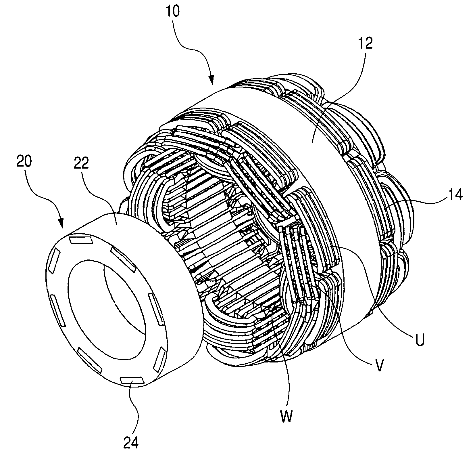
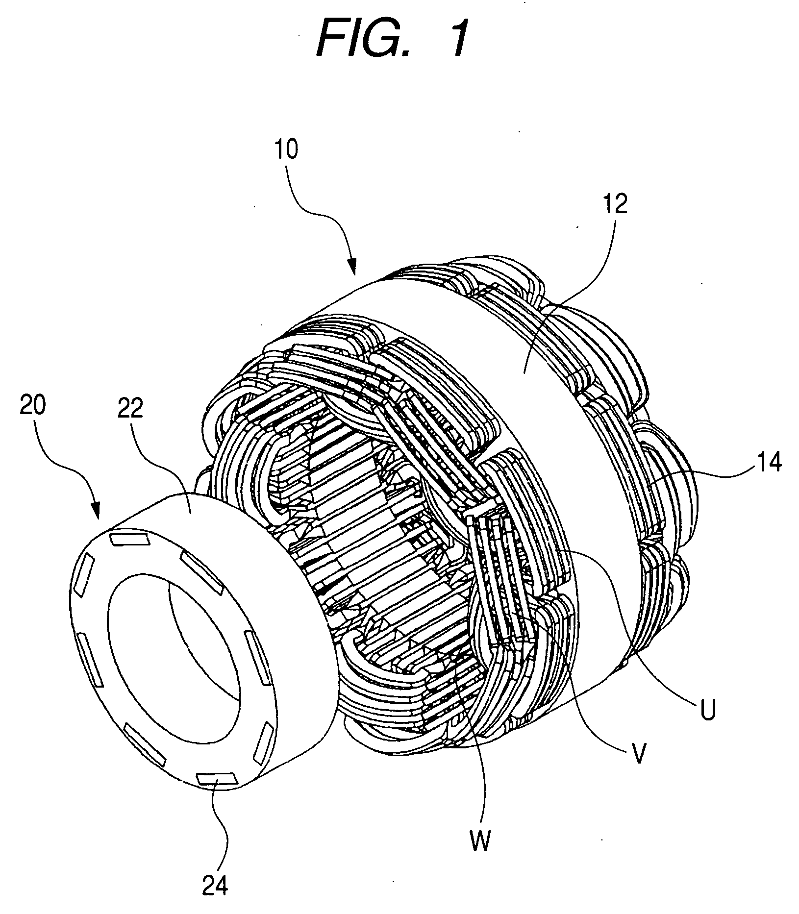
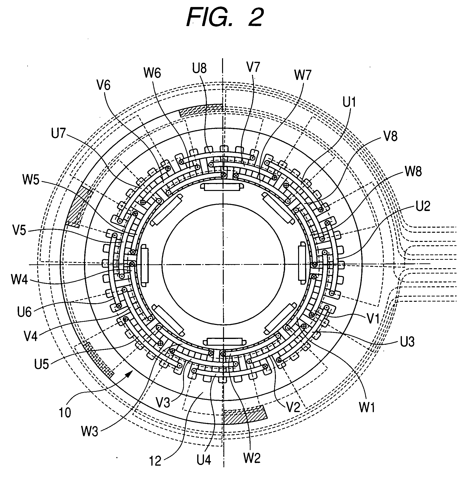
[0079] Referring to FIGS. 1 through 7, the following describes the structure of the rotating electrical machine as an embodiment of the present invention. In the first place, FIGS. 1 and 2 will be used to explain the structure of the rotating electrical machine according to the present embodiment. In the present embodiment, an 8-pole 48-slot synchronous machine of distributed winding equipped with a built-in permanent magnet type rotor will be taken as an example for the following explanation.

[0080]FIG. 1 is a perspective exploded view representing the structure of a rotating electrical machine as an embodiment of the present invention. FIG. 2 is a cross sectional view representing the structure of the rotating electrical machine as an embodiment of the present invention. It shows a cross section of a rotor given in FIG. 1, as viewed from the direction orthogonal to the axial direction. In the Figures, the same reference numerals indicate the same parts.

[0081] As shown in FIG. 1, ...


PUM

PropertyMeasurementUnit
Thicknessaaaaaaaaaa

Abstract

A stator coil, being a rectangular coil, is wound on a salient pole, striding across a plurality of slots, while being inserted sequentially through the inlet of a predetermined slot of the stator core. The stator coil comprises two slot inserts and to be inserted into the slot; two coil ends and located outside the end of the slot; and four twist sections arranged between the slot inserts and coil ends, processed by twisting. In the twist sections, twisting is applied to ensure that the surface of the rectangular coil in the second coil end will be opposite to the surface of the rectangular coil in the first coil end. The start of winding of the rectangular coil and the end of winding of the same coil are located on the same surface. Thereby, a rotating electrical machine with the large internal dimensions without increasing the external dimensions can be permitted.

Description

CLAIM OF PRIORITY [0001] The present application claims priority from Japanese application serial no. 2004-286571, filed on Sep. 30, 2004, the content of which is hereby incorporated by reference into this application. FIELD OF THE INVENTION [0002] The present invention relates to a rotating electrical machine and an electrical winding. BACKGROUND OF THE INVENTION [0003] In one of the prior art rotating electrical machines disclosed in the Patent Document 1, the three-phase stator coils of distributed winding are configured to ensure the coil end of a phase does not interfere with the coil end of other phase. This structure avoids the possibility of interference of the three-phase coil ends, and hence increases the length of a rotating electrical machine in the axial direction. Other known prior arts are disclosed in the following Patent Documents 2 through 5: [0004] Patent Document 1: Japanese Patent Laid-Open No. 2002-51489 [0005] Patent Document 2: Japanese Patent Laid-Open No. H...

Claims


Application Information

Patent Timeline
IPC IPC(8): H02K11/00H02K19/00H02K3/00H01F7/06
CPCY10T29/49073H02K3/12B60L50/15Y02T10/64Y02T10/7072
Inventor SAITO, YASUYUKIYASUHARA, TAKASHIKOBAYASHI, HIDEMITSU
Owner HITACHI LTD
Why Eureka
Try Eureka