Multi-frequency RFID apparatus and methods of reading RFID tags

a multi-frequency rfid and tag technology, applied in the field of multi-frequency antennas, can solve problems such as degrade the performance of antennas

Active Publication Date: 2006-03-30
SYMBOL TECH LLC
View PDF32 Cites 60 Cited by
  • Summary
  • Abstract
  • Description
  • Claims
  • Application Information

AI Technical Summary

Problems solved by technology

An additional concern is that a closer proximity of the RFID antenna to a part of a human body tends to degrade performance of the antenna.

Method used


Image

  • Multi-frequency RFID apparatus and methods of reading RFID tags
  • Multi-frequency RFID apparatus and methods of reading RFID tags
  • Multi-frequency RFID apparatus and methods of reading RFID tags

Examples


Embodiment Construction

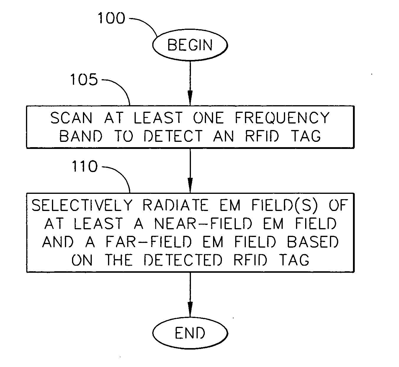
[0022] The following detailed description is merely exemplary in nature and is not intended to limit the invention or the application and uses of the invention. Furthermore, there is no intention to be bound by any expressed or implied theory presented in the preceding technical field, background, brief summary or the following detailed description.

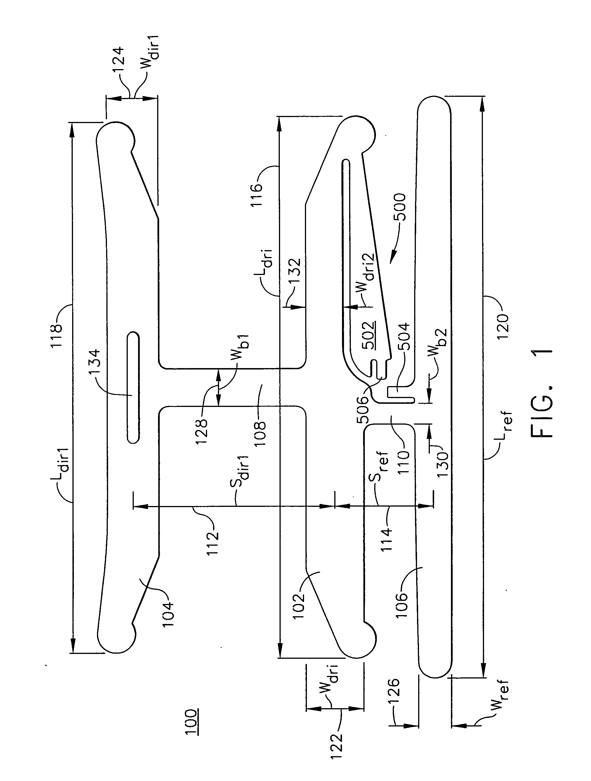
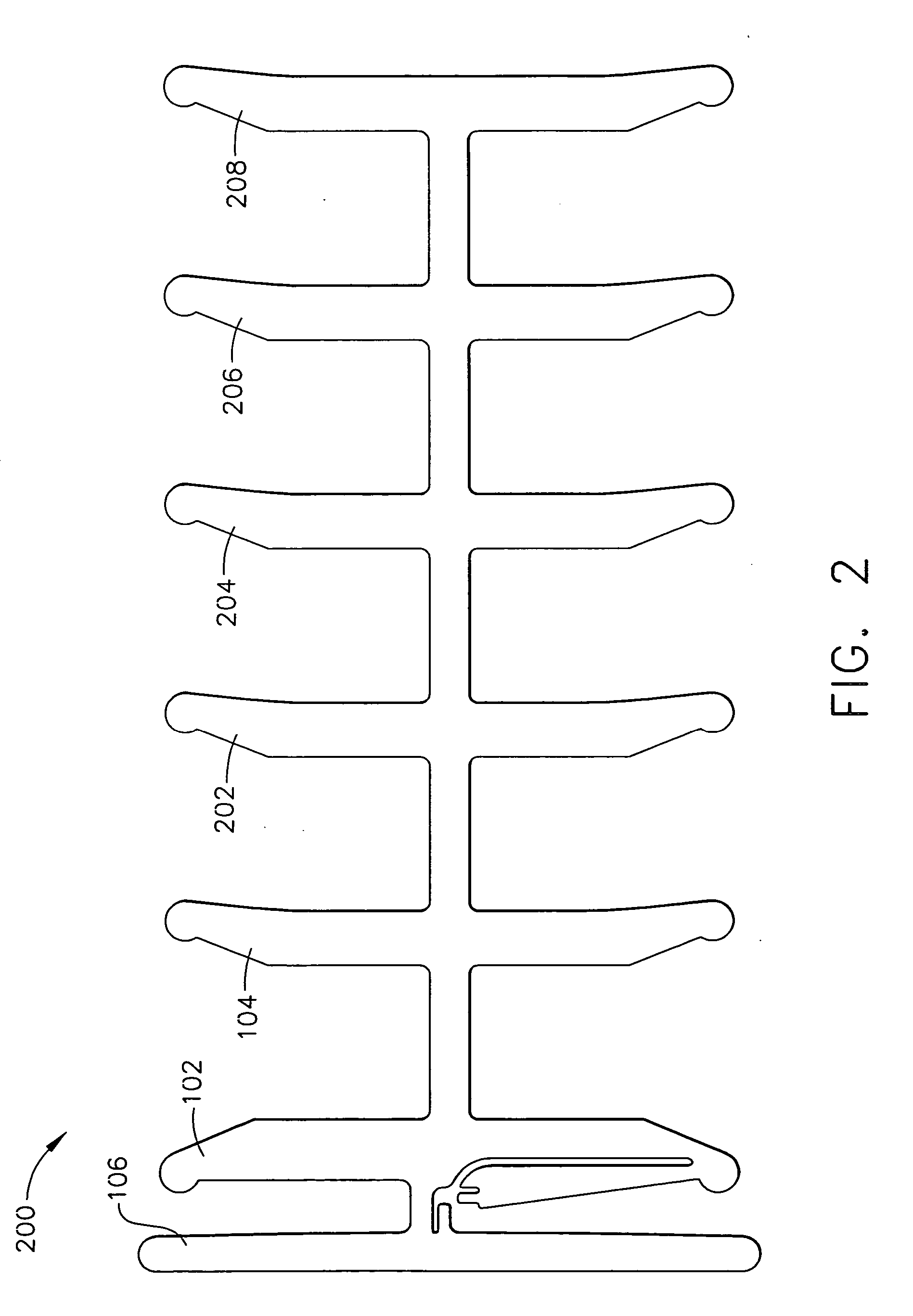
[0023] Referring to FIG. 1, a planar view of a directional antenna array 100 is provided in accordance with an exemplary embodiment of the present invention. Generally, the directional antenna array 100 includes a driven element 102 and at least one (1) parasitic element or director element 104, and may include a second parasitic element or reflector element 106 in addition to the director element 104 in one exemplary embodiment. While only two parasitic elements (i.e., director element 104 and reflector element 106) are shown in FIG. 1 in addition to the driven element 102, any number of parasitic elements can be provided in accordance ...


PUM


Abstract

A portable / handheld device is provided having a processing module configured to selectively operate a reading mode selected from a far-field mode and a near-field mode, and a directional antenna array coupled to the processing module. The directional antenna array includes a first antenna element configured to radiate electromagnetic (EM) radiation in a far-field, and a second antenna element coupled to the first antenna element. The second antenna element is configured to radiate EM radiation in a near-field. The second antenna element includes an antenna transducer configured to selectively cancel far-field EM radiation from the first antenna element. A method of reading inductively coupled radio frequency identification (RFID) tags is also provided having the steps of scanning at least one frequency band to detect a RFID tag, and selectively radiating one of a near-field electromagnetic (EM) field and a far-field EM field based on the detected RFID tag.

Description

TECHNICAL FIELD [0001] The present invention generally relates to a multi-frequency antenna, and more particularly relates to a directional antenna array for radio frequency identification (RFID). BACKGROUND [0002] Yagi-Uda antennas were originally described in the English language in an article written by H. Yagi (See H. Yagi, “Beam Transmission of the Ultra Short Waves,” Proc. IRE. Vol. 16, pp. 715-741, June 1928). These directional dipole antennas, which are commonly referred to as Yagi antennas, have been used for many years and in many applications. For example, the Yagi antenna has been used for reception of television signals, point-to-point communications and other electronics applications. [0003] The basic Yagi antenna typically includes a driven element, usually a half-wave dipole, which is driven from a source of electromagnetic energy or drives a sink of electromagnetic energy. The antenna also typically includes non-driven or parasitic elements that are arrayed with the...

Claims


Application Information

Patent Timeline
Patent Type & Authority Applications(United States)
IPC IPC(8): H04Q5/22H01Q5/15
CPCG06K7/0008H01Q1/22H01Q21/30H01Q21/28H01Q1/2216
Inventor KNADLE, RICHARD T. JR.CHARYCH, HALDURON, MARK WILLIAMBRIDGELALL, RAJ
Owner SYMBOL TECH LLC
Why Eureka
Try Eureka