Display device and the driving method of the same

Active Publication Date: 2006-03-30
SAMSUNG DISPLAY CO LTD +1
View PDF10 Cites 194 Cited by
  • Summary
  • Abstract
  • Description
  • Claims
  • Application Information

AI Technical Summary

Benefits of technology

[0024] To restrict the power consumption to a fixed value or less, in performing the display of an image in a reduced size by restricting the display area, an image brighter than an image when a display region is not restricted is displayed.
[0025] The driving voltage and the driving current are dynamically controlled in a state that the average brightness is lowered when the screen is bright as a whole and the average brightness is increased in an opposite case and he

Problems solved by technology

However, depending on the kind of the image to be displayed, the power consumption is increased and the power supply electricity easily exceeds an allowable limit thereof.
Here, in general, although an attempt to reduce the power consumption by decreasi

Method used


Image

  • Display device and the driving method of the same
  • Display device and the driving method of the same
  • Display device and the driving method of the same

Examples


Example

Embodiment 1

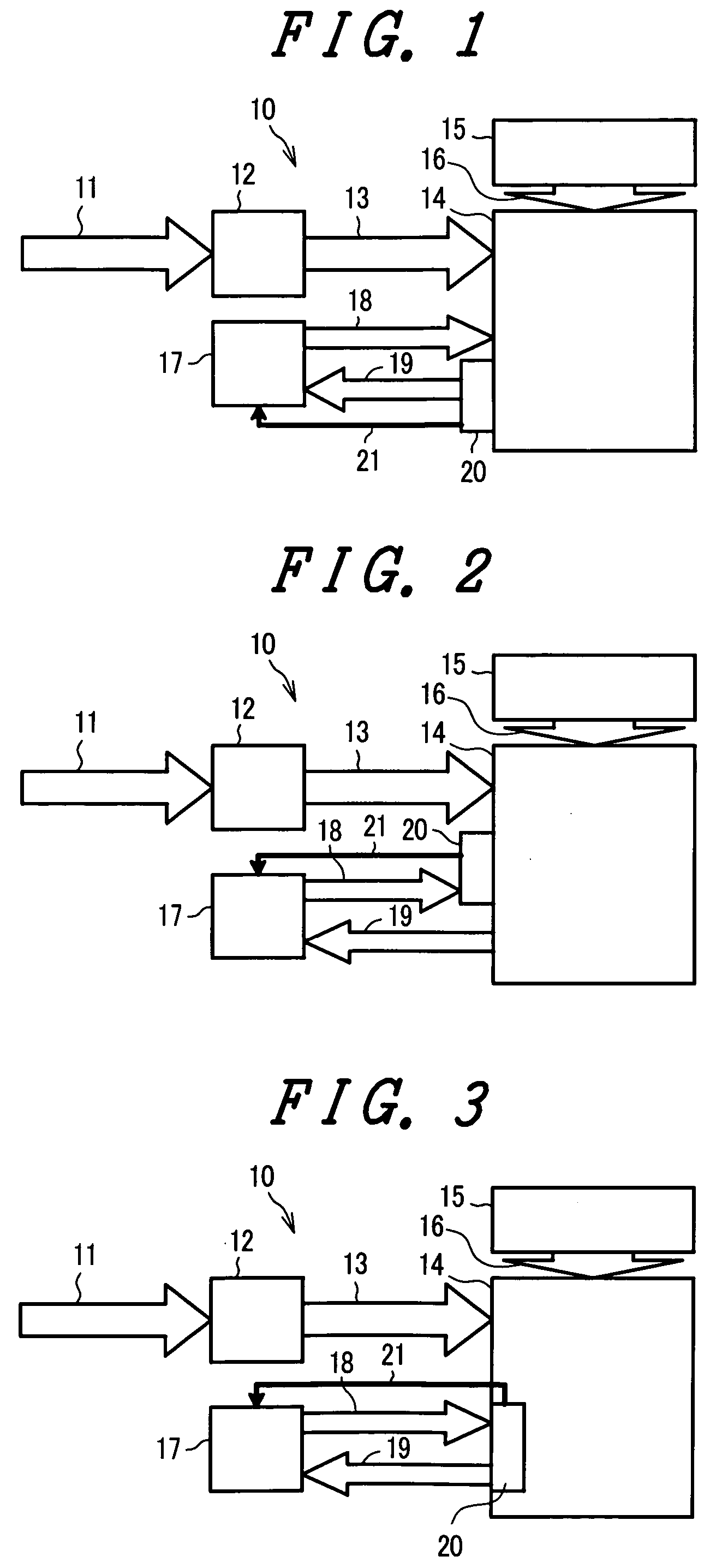
[0036]FIG. 1 is a schematic view of a display device 10 according to the present invention, wherein an input image signal 11 is processed at a signal processing circuit 12, and a processed image signal 13 is supplied to a display panel 14. The image signal 13 inputted to the display panel 14 is displayed on the display panel 14 in response to a control signal 16 which is supplied to the display panel 14 from a control circuit 15.

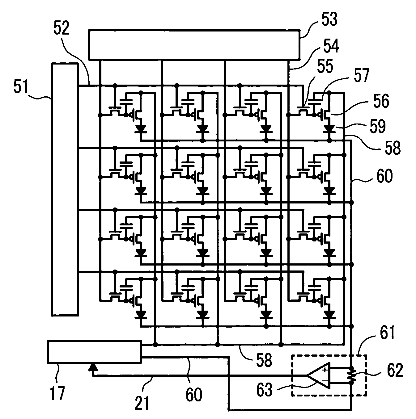
[0037] On the other hand, a driving power 18 which constitutes a driving voltage and a driving current from a power supply circuit 17 is supplied to the display panel 14 and hence, a luminous state of a plurality of organic EL elements which constitute self-luminous elements arranged inside the display panel 14 is controlled. A cathode current 19 of the plurality of organic EL elements whose luminous state is controlled is detected by a detection part 20 and a detection signal 21 is fed back to the power supply circuit 17. Further, the cathode ...

Example

Embodiment 2

[0043] In the embodiment 1, the detection signal 21 indicative of the brightness condition of the display image is obtained from the detection part 20 which directly detects the driving current which corresponds to the cathode current or the anode current of the organic EL elements of the display panel 14. In this embodiment 2, the detection signal 21 indicative of the brightness condition of the display image is obtained from a detection part which detects an image signal.

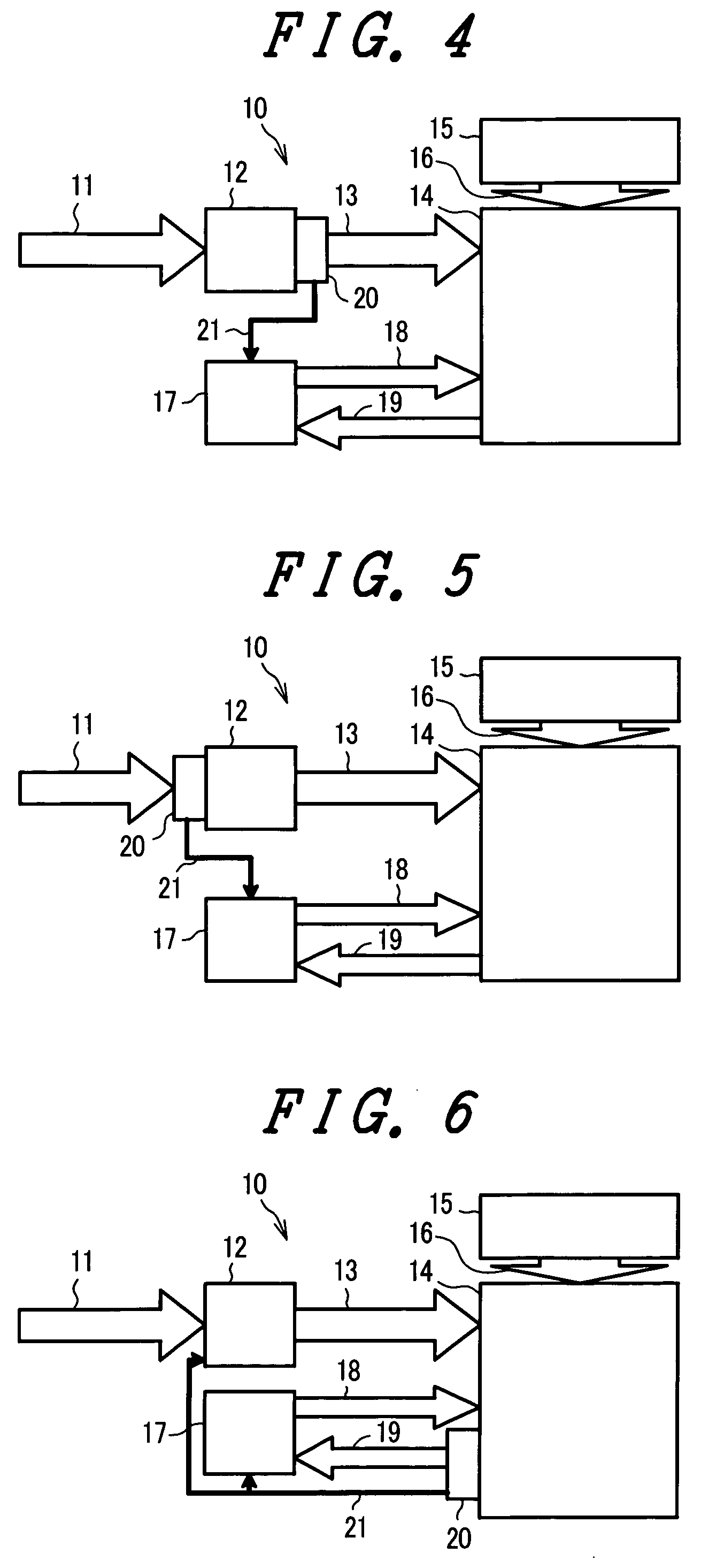
[0044]FIG. 4 is a schematic view of the display device of the present invention, wherein the display device of this embodiment 2 differs from the display device of the embodiment 1 with respect to a point that the detection part 20 detects a brightness level of the image signal 13 and the display device of the embodiment 2 is equal to the display device of the embodiment 1 with respect to other constitutions. In FIG. 4, the detection part 20 detects the brightness level of the image signal 13 and con...

Example

Embodiment 3

[0048] This embodiment is characterized in that, in the embodiment 1, the detection signal 21 fed back to the power supply circuit 17 is further fed back to the signal processing circuit 12.

[0049]FIG. 6 is a schematic view of the display device according to the present invention and corresponds to FIG. 1. The display device shown in FIG. 6 differs from the display device shown in FIG. 1 with respect to a point that the detection signal 21 is fed back to the signal processing circuit 12. In FIG. 6, the detection signal 21 from the detection part 20 is fed back to the power supply circuit 17 and the signal processing circuit 12 and hence, it is surely possible to control the driving power 18 from the power supply circuit 17 to a fixed value or less. Accordingly, it is surely possible to control the power consumption of the display panel 14 to a fixed value or less. Further, in FIG. 2 and FIG. 3, the detection signal 21 may be fed back to the signal processing circuit 12....


PUM


Abstract

A plurality of organic EL elements which are arranged on a display panel lowers the brightness along with a lapse of light emitting time and hence, the power consumption is increased to maintain the brightness. However, the increase of the power consumption shortens a lifetime of the organic EL elements. To overcome this drawback, a power supply circuit which drives the display panel has a function of controlling an electric power supplied to the display panel to a fixed value or less in response to a detection signal from a detection part which detects a cathode current of the organic EL elements.

Description

CROSS-REFERENCE TO RELATED APPLICATIONS [0001] The disclosure of Japanese Patent Application No. 2004-279567 filed on Sep. 27, 2004 including the specification, drawings and abstract is incorporated herein by reference in its entirety. BACKGROUND OF THE INVENTION [0002] 1. Field of the Invention [0003] The present invention relates to an energy-saving display device and a driving method of the same. [0004] 2. Description of the Related Arts [0005] As a display device which displays an image, particularly, as a thin flat panel display, there has been known a self-luminous image display device such as a PDP (Plasma Display Panel), a FED (Field Emission Display) or an organic EL (Organic Electro Luminescence) display. [0006] In such a self-luminous image display device, a following patent literature 1 discloses a display device which performs a control to lower the display brightness of a screen in displaying an image of high average brightness thus realizing, without damaging a displa...

Claims


Application Information

Patent Timeline
IPC IPC(8): G09G3/30H05B44/00
CPCG09G3/20G09G3/3233G09G2300/0842G09G2360/16G09G2320/043G09G2320/0626G09G2330/021G09G2320/029
Inventor SATO, TOSHIHIROAKIMOTO, HAJIMEKASAI, NARUHIKOTOKUDA, NAOKI
Owner SAMSUNG DISPLAY CO LTD
Why Eureka
Try Eureka