
Image forming apparatus, image forming method, and recording medium

a technology of image forming and forming methods, applied in the field of image forming apparatuses, image forming methods, and recording media, can solve the problems of reduced use of methods, reduced gray level per pixel, and reduced image quality,

Inactive Publication Date: 2006-03-30
RICOH KK
View PDF8 Cites 17 Cited by
  • Summary
  • Abstract
  • Description
  • Claims
  • Application Information

AI Technical Summary

Benefits of technology

[0036] An embodiment of the present invention provides an image forming apparatus, an image forming method, and a recording medium to solve at least one problem described above. In a preferred embodiment, the present invention provides an image forming apparatus capable of outputting images while eliminating color moire that occurs between a Y pattern and CMK patterns as well as color moire that occurs among CMK patterns, an image forming method, and a recording medium.

Problems solved by technology

However, in image forming apparatuses (including electrophotographic systems) that form images (so-called hard copy) on paper, available gray levels per pixel are in fact very limited.
Although there have been methods for dithering images of the four colors to have the same periodic structure, these types of methods are less used today because the colors are more likely to vary due to variation of positions where the colors are superposed.
If this interference pattern which is also called color moire appears in a low-frequency band (i.e., if the beat has a low frequency) and is visually perceived, users may notice a reduction in image quality due to the interference pattern.
In dot concentration type dither matrices, because a growth center needs to have a square periodic structure, the number of screen lines and the screen angle available are limited.
The production process of line type dither matrices includes manual work requiring specialized skills, which make it difficult to produce all the dither matrices as desired.
Even if more matrices become available, it is impractical to actually produce the available matrices and verify their effects in order to find a dither set with reduced color moire.
Also, even if line type dither matrices can be produced as desired by solving the above-described problem with dither matrix production, selecting a dither matrix set with reduced color moire is not easy.
It is very difficult to select a dither matrix set with reduced color moire from such numerous numbers of dither sets.
Outputting (printing out) images using all these combinations and verifying output images are almost impossible because of the large number of combinations.
This method, however, requires a long calculation time because a large image area needs to be processed to detect intensity variation of color moire due to its low frequency.
Therefore, it is almost impossible to perform such a calculation for all the numerous combinations.
However, as an infinite series is included in a first-order Bessel function in the coefficient of Fourier series expansion used in this method, color moire evaluation by this method may require quite a long time.
Therefore, it also seems to be almost impossible to perform such a calculation for all the dither sets.
The problem specific to line dither matrices is color moire that occurs in tertiary colors.
This makes selection of a dither set having reduced color moire more difficult.
That is, dot screens, which have little screen arrangement flexibility as described above, are not suitable for electrophotographic printing systems.

Method used


Image

  • Image forming apparatus, image forming method, and recording medium
  • Image forming apparatus, image forming method, and recording medium
  • Image forming apparatus, image forming method, and recording medium

Examples


embodiment 1

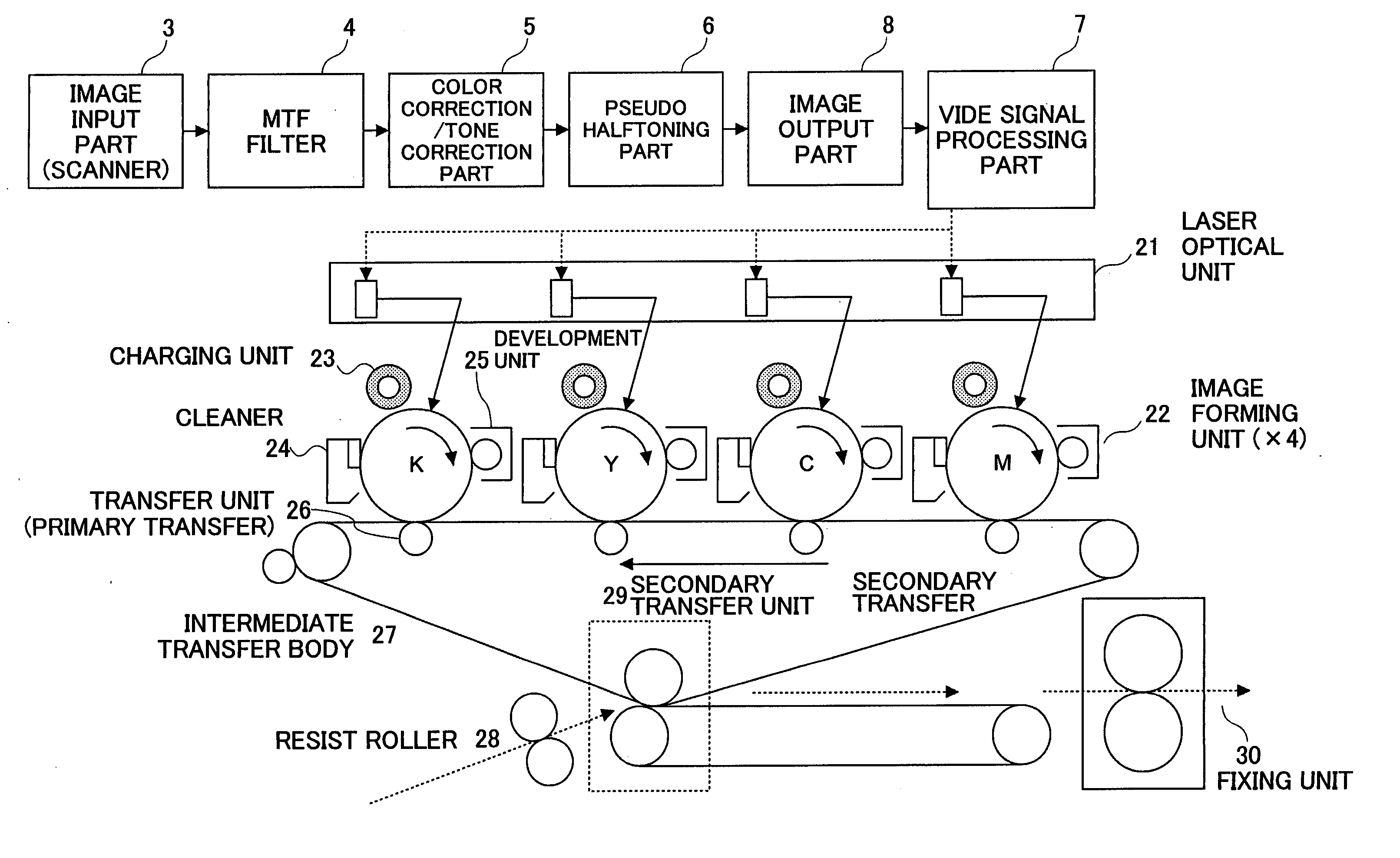
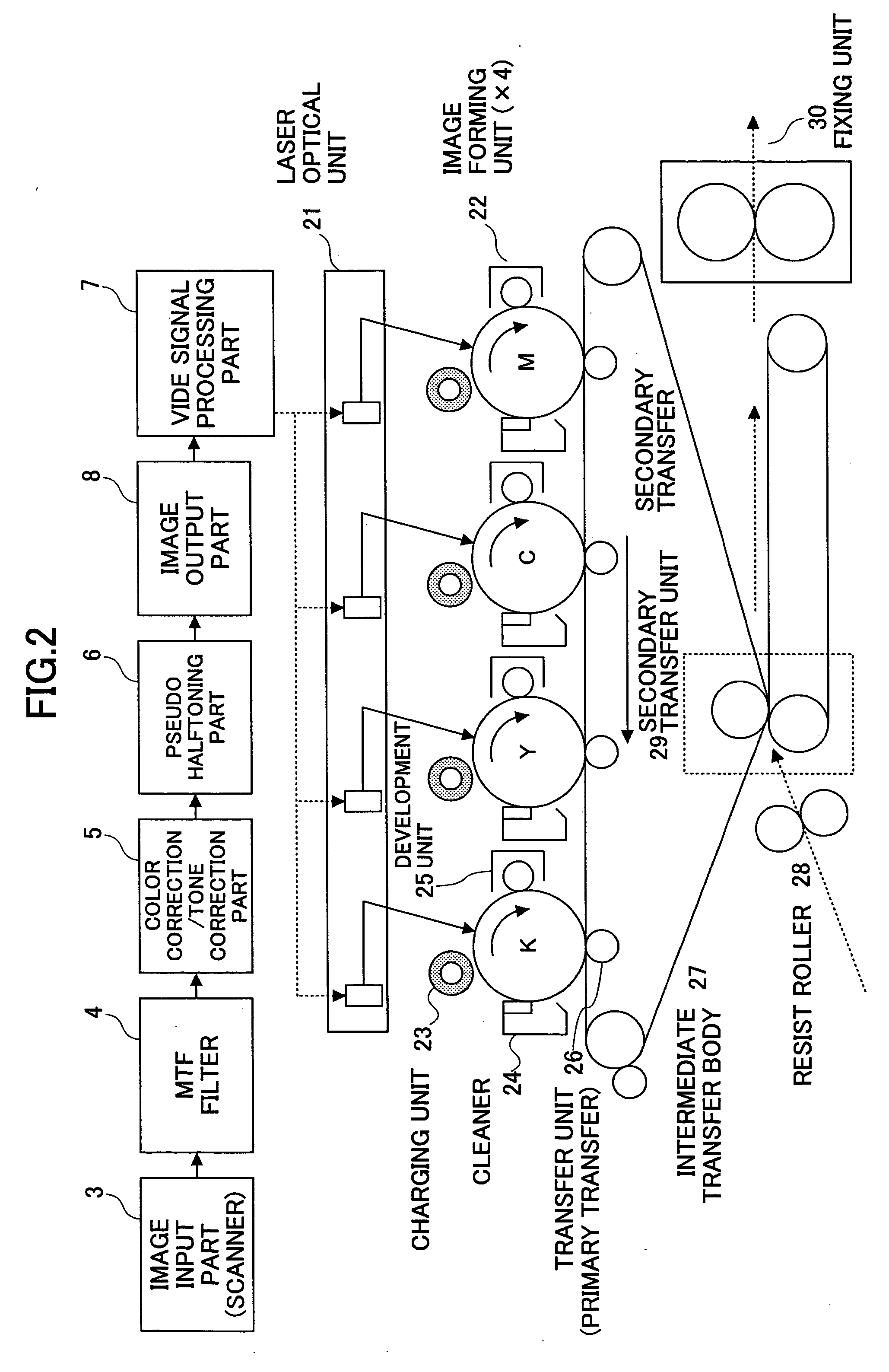
[0052]FIG. 2 is a schematic diagram illustrating an image forming apparatus according to the present invention. The image forming apparatus of FIG. 2 is a full-color image forming apparatus that forms an image by superposing color component images of four colors of cyan (C), magenta (M), yellow (Y), and black (K) onto a recording sheet. According to Embodiment 1, four image forming units 22 corresponding to color components of C, M, Y, and K are arranged as shown in FIG. 2. Color component images formed by the image forming units 22 are sequentially transferred onto an intermediate transfer body (intermediate transfer belt) 27 arranged in contact with the four image forming units 22. The intermediate transfer body 27 is rotated by a not-shown drive unit (motor or gear) at predetermined timings such that the color component images are superposed at predetermined positions on the intermediate transfer body 27. The color component images superposed on the intermediate transfer body 27 ...

embodiment 2

[0155] Dither matrices of four colors of CMYK of Embodiment 2 are shown in Table 29. As in Embodiment 1, calculation of color moire scores of secondary colors and tertiary colors is performed in Embodiment 2, of which results are shown in Table 30.

TABLE 29No.Line [lpi]Angle [deg.]a0xa0ya1xa1y0191.726.6211−31191.763.4123−12191.7116.6−12313191.7153.4−2113

[0156]

TABLE 30MoireColorlineMoire anglemoireColor moireCombination[lpi][deg.]VTFamplitudescoreSecondary color0-1121.245.00.08500.1260.01120-2271.171.60.00100.1260.00010-3171.40.00.01700.1260.00221-2171.490.00.01700.1260.00221-3271.118.40.00100.1260.00012-3121.2135.00.08500.1260.0112Tertiary color0-1-285.70.00.25600.0320.00860-1-385.790.00.25600.0320.00860-2-385.790.00.25600.0320.00861-2-385.70.00.25600.0320.0086

[0157] According to Embodiment 2, Table 30 indicates that among six secondary colors and four tertiary colors, a tertiary color of the dither matrix combination of 0-1 and a tertiary color of the dither matrix combination of ...

embodiments 3-20

Embodiment 3

[0159] In this embodiment, a combination of dither matrices shown in Table 31 is employed in an image forming apparatus having the same configuration as the image forming apparatus of Embodiment 1.

TABLE 31LineAngleNo.[lpi][deg.]a0xa0ya1xa1y0189.718.4311−31189.7108.4−13312191.763.4123−13191.7153.4−2113


PUM


Abstract

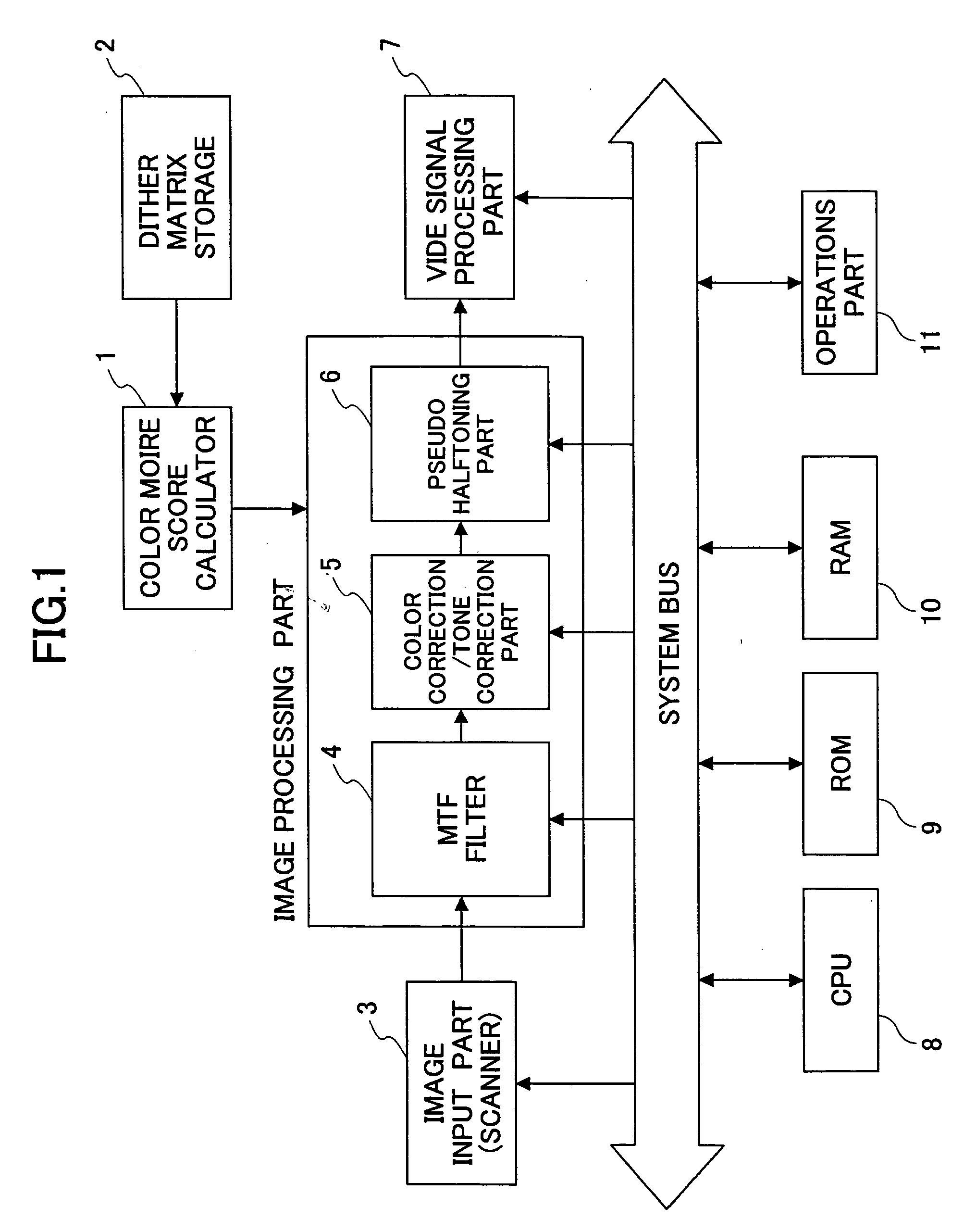
An image forming apparatus is disclosed. A color moire score calculator selects a combination (a dither set) of four dither matrices from plural types of dither matrices stored in a dither matrix storage, and calculates color moire scores of secondary colors and tertiary colors. Dither processing is performed in a pseudo-halftoning part using a dither set having a preferable color moire score.

Description

BACKGROUND OF THE INVENTION [0001] 1. Field of the Invention [0002] The present invention relates to an image forming apparatus for performing pseudo halftoning using a dither method, an image forming method, and a recording medium. [0003] 2. Description of the Related Art [0004] Image data that are input into image forming apparatuses include, in the case of a gray-scale image such as a photograph, multivalued data having 8 through 12 bits per pixel. However, in image forming apparatuses (including electrophotographic systems) that form images (so-called hard copy) on paper, available gray levels per pixel are in fact very limited. In order to solve this problem, hard copy apparatuses apply higher resolution, such as 600 dpi and 1,200 dpi, so as to modulate the image intensity by using plural pixels according to an area modulation scheme, thereby representing halftone images in a pseudo manner. Such a processing of converting input image data into a pseudo halftone image is known a...

Claims


Application Information

Patent Timeline
IPC IPC(8): H04N1/405
CPCH04N1/52H04N1/4058
Inventor YASUTOMI, KEI
Owner RICOH KK
Learn More